Direct-driving circular loom magnetic suspension shuttle device

A circular loom, direct-drive technology, applied to circular looms, looms, textiles, etc., can solve problems such as lack of dynamic control means, affect work stability, and easy damage to parts, so as to reduce damage and improve efficiency , the effect of reducing energy consumption

Inactive Publication Date: 2007-11-07
朱根山 +1
View PDF5 Cites 6 Cited by
  • Summary
  • Abstract
  • Description
  • Claims
  • Application Information

AI Technical Summary

Problems solved by technology

Due to the lack of dynamic control means, it will affect the work stability
[0008] Although the circular loom mentioned above adopts some principles of magnetic force and magnetic levitation, there are some unav

Method used


Image

  • Direct-driving circular loom magnetic suspension shuttle device
  • Direct-driving circular loom magnetic suspension shuttle device
  • Direct-driving circular loom magnetic suspension shuttle device

Examples


Embodiment Construction

[0026] Further description will be made below in conjunction with the embodiments and accompanying drawings.

[0027] See attached picture.

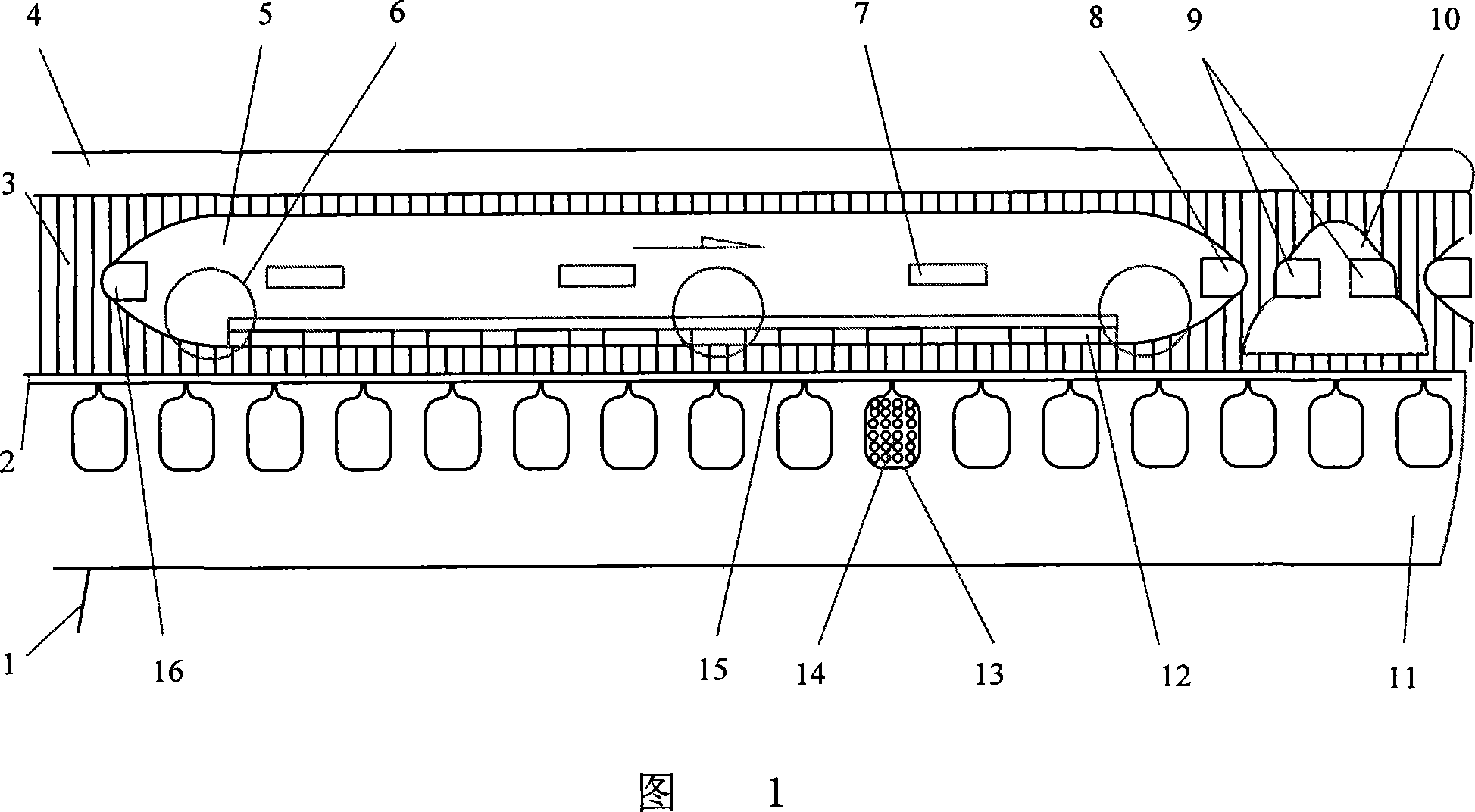
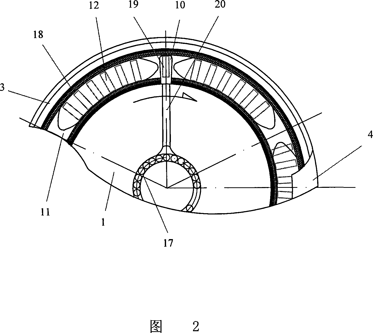
[0028] Fig. 1, 2 are the embodiments of the magnetic levitation shuttle device of this direct drive type circular loom. It includes frame 1, rail 2, gate rail ring 3, upper door ring 4, shuttle 5, shuttle bar 20, magnetic head 8, 16, magnetic block, guide wheel, motor and its electrical control device, wherein the motor adopts A permanent disk surface motor is provided, and its primary stator 11 is integrated with the frame 1, the gate rail ring 3, and the upper door ring 4; its permanent magnet secondary mover 12 is combined by a separated permanent magnet and pure iron (also can use Composite soft magnetic material) is arranged on the bottom surface of the shuttle 5, corresponding to the primary electromagnetic coil; the shuttle 5 is arranged on the inner side of the gate rail 3 and on the table track of the annular primary 11; There...


PUM


Abstract

The present invention discloses one kind of magnetically suspended shuttle device for directly driven circular loom. The magnetically suspended shuttle device includes a frame, tracks, a gate rail ring, an upper gate ring a shuttle, a shuttle separating rod, magnetic heads, magnetic blocks, a guide pulley and a permanent magnet motor. The magnetically suspended shuttle device has simplified structure, less mechanical noise, capacity of improving weaving quality, low power consumption a high efficiency, and is suitable for use in general-purpose circular loom.

Description

technical field [0001] The present invention relates to circular looms. Specifically, it is an electromagnetic levitation shuttle device powered by a permanent disk surface synchronous motor on a circular loom. Background technique [0002] In the disclosed "soft belt circular loom" of Chinese patent 97238569. X, the single-shuttle mechanism interlaced up and down is transformed into a double-shuttle mechanism of circular operation, thereby improving work efficiency. [0003] Thereafter, the "magnetic propulsion device for circular loom" disclosed in Chinese patent 99212966.4 was designed to solve the problem of the circular movement of the shuttle and the up-and-down weaving movement of the warp, because there is no distance between the pusher assembly and the shuttle, resulting in excessive resistance to the passage of the warp, and the gear was changed. The rotation is driven by magnetic force, which reduces mechanical wear, improves the wor...

Claims


Application Information

Patent Timeline
IPC IPC(8): D03D37/00D03D49/44
Inventor 叶云岳朱根山范承志
Owner 朱根山
Why Eureka
Try Eureka