
Silencer

A muffler and compensator technology, applied in intake mufflers, mufflers, machines/engines, etc., can solve problems such as design frequency imbalance, insufficient effectiveness, weakened damping effect, etc., and achieve the effect of reducing transmission noise

Active Publication Date: 2005-03-09
TURBO SYST SWITZERLAND LTD
View PDF1 Cites 10 Cited by
  • Summary
  • Abstract
  • Description
  • Claims
  • Application Information

AI Technical Summary

Problems solved by technology

This results in an offset of the design frequency and a reduction in the damping effect
Therefore, conventional resonance mufflers are not effective enough for fluid velocity up to 100 m / s
[0005] Therefore, conventional resonators arranged in flow channels, such as described in JP 10-318194, do not work as expected due to high flow rates

Method used


Image

  • Silencer
  • Silencer
  • Silencer

Examples


Embodiment Construction

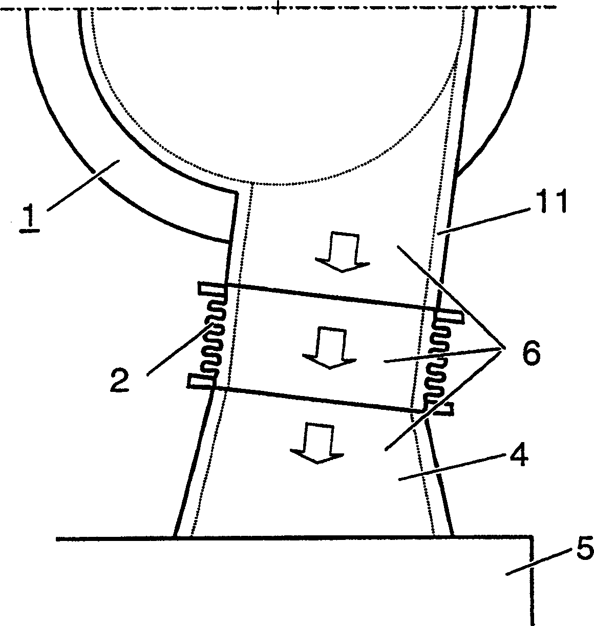
[0021] figure 1 Schematic representation of part of an internal combustion engine with a turbocharger. For example, the internal combustion engine is a large diesel engine, such as is used in ships or stationary power plants. The turbocharger comprises a compressor 1 into which air is drawn in and compressed in order to be subsequently supplied to a charge air cooler 5 of the internal combustion engine via a compressor outlet 11 and a connecting line 4 . In the city, the compressed air flows in the direction of the arrow through a flow channel 6 which, depending on the arrangement of the turbocharger on the internal combustion engine, can be longer or shorter and can include one or more tubular intermediate pieces. One of these intermediate pieces is the schematically shown compensator part 2 .

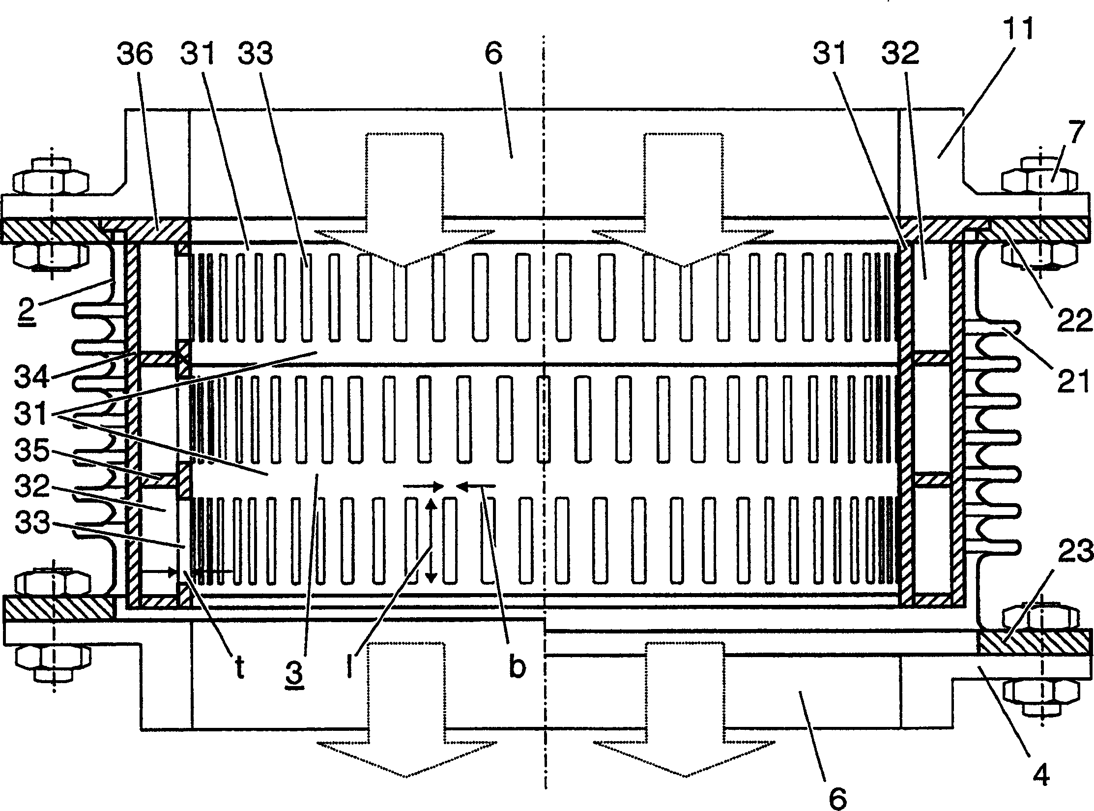
[0022] exist figure 2 The compensator part, shown enlarged in , comprises a compensating element 21 which is formed by an elastic sheet and is arranged between two fastening flang...


PUM


Abstract

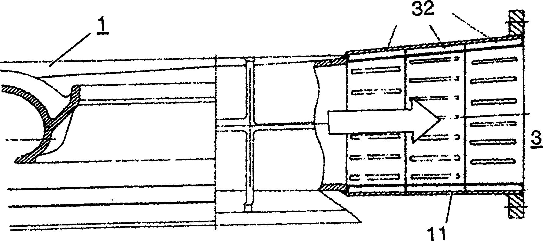
Openings in the covering sheet of the chamber (32) are formed as slots orientated along the flow direction. The open areas (33) amount to about 6-14% of the total area (31) of the chamber. Slot length to width ratio exceeds 3, and the slots differ in length.

Description

technical field [0001] The invention relates to the field of exhaust gas turbochargers for internal combustion engines. The invention relates to a resonance muffler according to the preamble of claim 1 . Furthermore, the invention relates to an internal combustion engine having such a resonance muffler. Background technique [0002] The compressor is the key to the noise generated by the exhaust gas turbocharger of the internal combustion engine. In particular, high noise levels are introduced into the air supply line on the output side of the compressor, and there has hitherto been no solution for damping such noise satisfactorily. [0003] The problem with absorbers arranged in the flow channel is that the high flow velocity of the compressed air causes the sound-absorbing material to be blown away through the perforated plate cover. Placing the material in the usually downstream cooler can cause the cooler to become clogged. Likewise, fibrous materials based on minera...

Claims


Application Information

Patent Timeline
Patent Type & Authority Applications(China)
IPC IPC(8): F01N1/02F01N1/08F02B37/00F02M35/12F04D29/44F04D29/66
CPCF02M35/10144F02M35/1266F02M35/12F02M35/10137F01N1/026F02M35/1216F02B37/00F02M35/10157Y02T10/12F01N1/02F01N1/08
Inventor G·库德尔纳特施H·-J·费尔德
Owner TURBO SYST SWITZERLAND LTD
Learn More