Isothermal power

a technology of isothermal power and expansion device, which is applied in the direction of steam engine plants, machines/engines, mechanical equipment, etc., can solve the problems that cannot be done with an adiabatic expansion device, and achieve the effect of reducing mechanical losses in the compression and expansion device and effectively producing an approximate isothermal compression

Inactive Publication Date: 2008-10-30
PRUEITT MELVIN L
View PDF7 Cites 37 Cited by
  • Summary
  • Abstract
  • Description
  • Claims
  • Application Information

AI Technical Summary

Benefits of technology

024]It is another object of the present invention to provide means for reducing mechanical losses in the compression and expansion devices.<
025]It is another object of the present invention to provide methods to effectively produce approximate isothermal compression and expansion of gases.<

Problems solved by technology

This cannot be done with an adiabatic expander, because the vapor exhaust from the adiabatic expander is normally cooler than the superheat temperature.

Method used


Image

  • Isothermal power
  • Isothermal power
  • Isothermal power

Examples


Embodiment Construction

Single-Phase Gas Isothermal Heat Engine

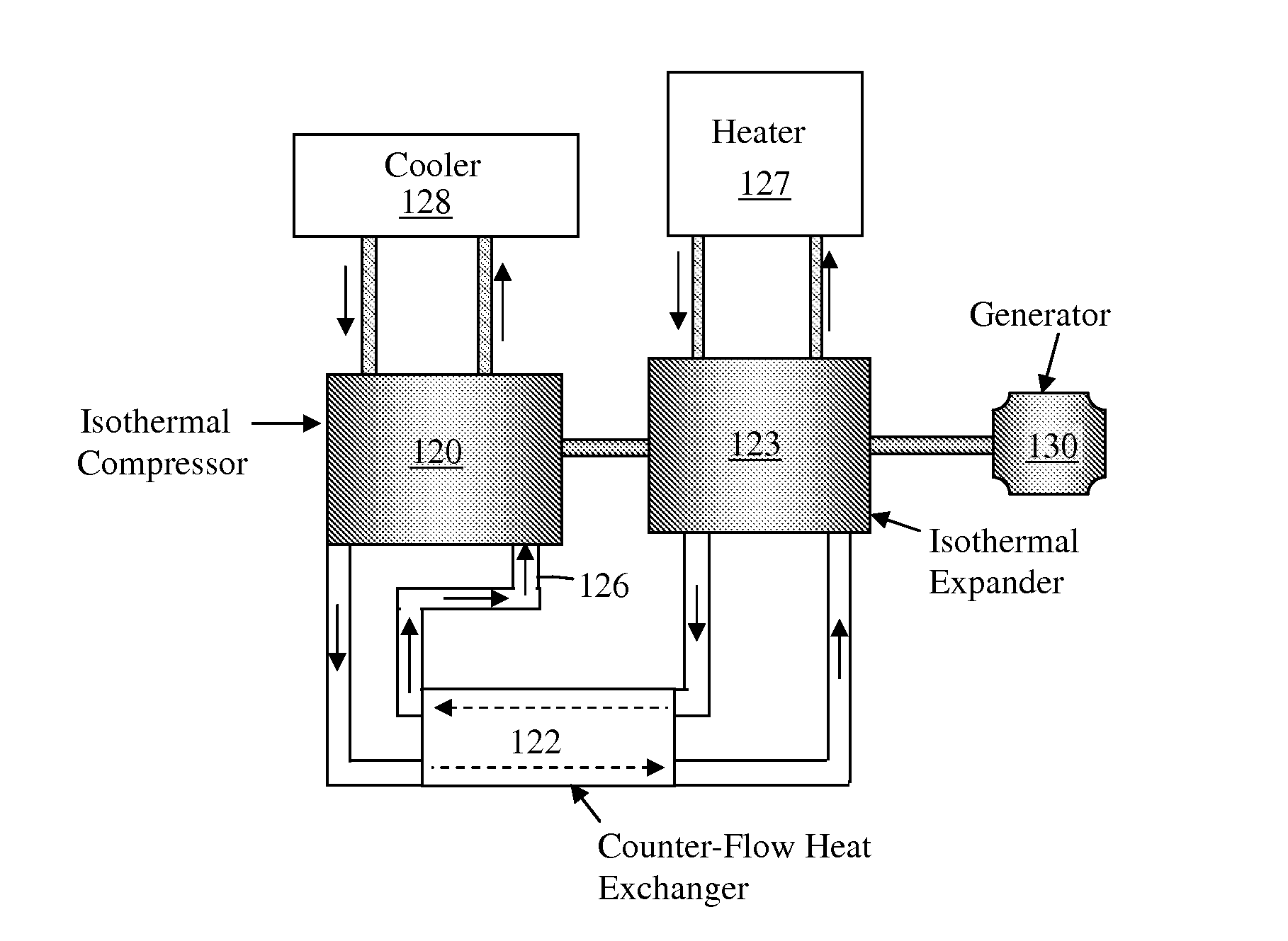
[0037]FIG. 1 shows a layout for the single-phase gas isothermal engine system. The gas is compressed in the isothermal compressor. In order to keep the gas at constant temperature, a cooler is necessary, since compression of a gas tends to heat it.

[0038]For efficient heat transfer, the cooler can supply a liquid to channels beneath the surfaces in the compressor. The liquid evaporates as it removes heat from the surfaces. The vapor flows to the cooler, where it is condensed and returned to the compressor.

[0039]For adequate heat flow, the heater should supply heat at slightly higher temperature than the isothermal temperature of the expander, and the cooler should supply a fluid that is at slightly lower temperature than the compressor isothermal temperature.

[0040]In FIG. 1, the isothermal compressor 120 draws air (or other gas) in through pipe 126 and compresses it. The compressed gas from the isothermal compressor then flows through the counte...


PUM


Abstract

This invention provides means for producing power by using isothermal compressors and isothermal expanders. One embodiment has an isothermal compressor that compresses air (or other gas), passes the air through a counter-flow heat exchanger, which heats the air, uses the heated air to drive an isothermal expander for power generation, and transfers the expander exhaust back through the counter-flow heat exchanger to heat the input air to the expander. Another embodiment has a boiler that produces vapor that flows through a counter-flow heat exchanger to superheat the vapor. The vapor then flows through an isothermal expander for power generation. The exhaust from the isothermal expander flows back through the counter-flow heat exchanger to supply heat to the vapor coming from the boiler and then flows through another heat exchanger that preheats the feed liquid flowing to the boiler.

Description

CROSS-REFERENCE TO RELATED APPLICATION[0001]This claims priority to and the benefit of Provisional U.S. Patent Application Ser. No. 60 / 914,036, filed Apr. 26, 2007, the entirety of which is hereby incorporated herein by reference.BACKGROUND OF THE INVENTION[0002]Most of the heat engines in use today use adiabatic expansion of gases to produce power. The Rankine, Brayton, Otto cycles, and others use adiabatic expansions, and some of them also use adiabatic compressions. This disclosure shows that isothermal expansion and compression have some important efficiency advantages.[0003]The isothermal cycle can use a working fluid such as water, ammonia, or propylene that are boiled and then expanded isothermally in an engine to produce power. The vapors are then condensed back to a liquid to repeat the cycle. It can also use a gas such as air or helium that can be compressed isothermally, heated, and then expanded isothermally in an engine that drives an electric generator or drives some o...

Claims


Application Information

Patent Timeline
Patent Type & Authority Applications(United States)
IPC IPC(8): F01K25/00F01K27/00
CPCF01K27/00
Inventor PRUEITT, MELVIN L.
Owner PRUEITT MELVIN L
Why Eureka
Try Eureka