Compressor having a small-width portion and a large-width portion in an inner circumferential sliding surface of a swinging roller

a compression machine and sliding surface technology, applied in the field of compression machines, can solve the problems of inability to provide a large-width portion and a small-width portion in the inner circumferential sliding surface of the compression machine, and achieve the effects of ensuring enough lubrication, reducing manufacturing costs of the compression machine, and improving product precision

Inactive Publication Date: 2009-07-07
DAIKIN IND LTD
View PDF10 Cites 3 Cited by
  • Summary
  • Abstract
  • Description
  • Claims
  • Application Information

AI Technical Summary

Benefits of technology

[0006]An object of the present invention is to provide a compressor which is capable of reducing mechanical loss by reducing the viscous shear loss of lubricating oil between the outer circumferential sliding surface of the eccentric portion of the drive shaft and the inner circumferential sliding surface of the roller, and moreover which is easy to machine, low in price and high in precision.

Problems solved by technology

This makes it impossible to provide a small-width portion and a large-width portion in the inner circumferential sliding surface of the roller, with the result that a small-width portion and a large-width portion are provided in the outer circumferential sliding surface of the eccentric portion in spite of a difficulty in mechanical machining.

Method used


Image

  • Compressor having a small-width portion and a large-width portion in an inner circumferential sliding surface of a swinging roller
  • Compressor having a small-width portion and a large-width portion in an inner circumferential sliding surface of a swinging roller
  • Compressor having a small-width portion and a large-width portion in an inner circumferential sliding surface of a swinging roller

Examples


Embodiment Construction

[0038]Hereinbelow, concrete embodiments of the swing compressor according to the present invention are described in detail with reference to the accompanying drawings.

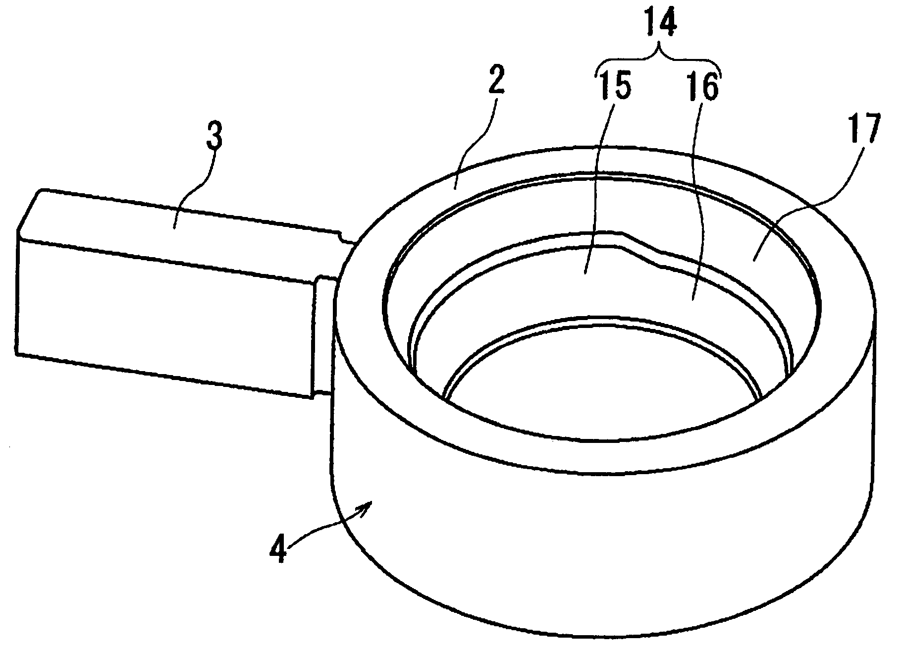
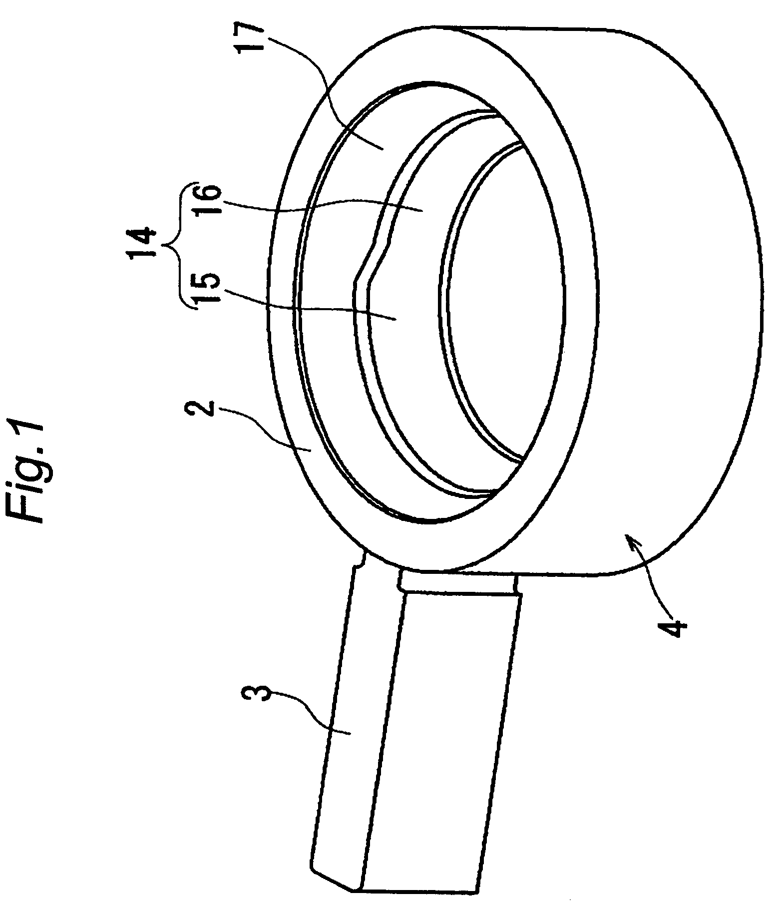
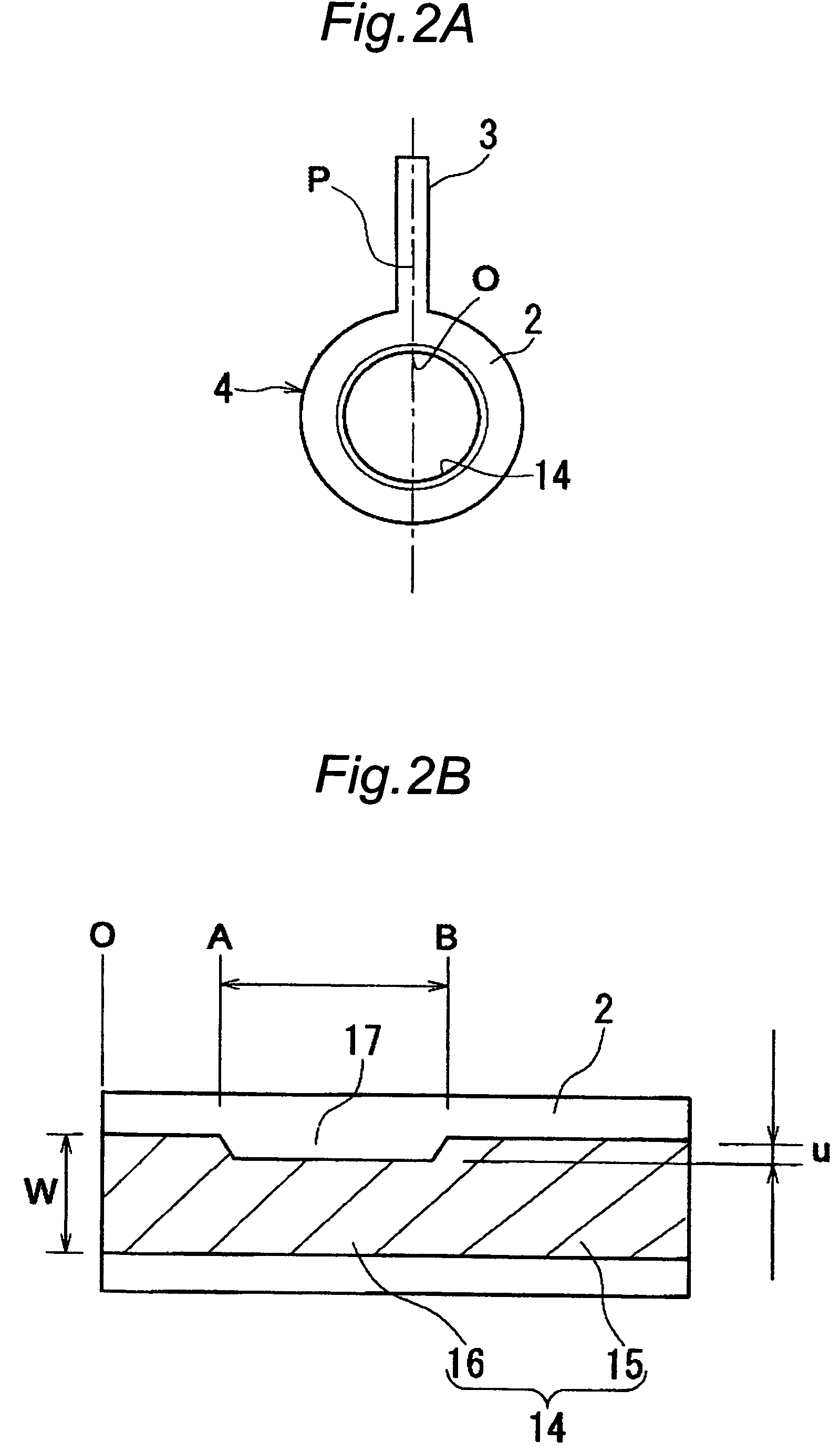
[0039]FIGS. 3A, 3B, 3C and 3D are schematic plan views showing main part of the swing compressor. This swing compressor is intended for use, for example, as a compressor for refrigerators using HFC (hydrofluorocarbon) base refrigerants. The swing compressor has a piston 4 integrally made up of a generally cylindrical-shaped roller 2 and a blade 3 that protrudes radially outward of the roller 2. An outer circumferential cylindrical surface and an inner circumferential cylindrical surface of the roller 2 are concentric with each other. The inner circumferential cylindrical surface, i.e. inner circumferential sliding surface, of the roller 2 of the piston 4 is slidably fitted to the outer circumferential sliding surface of an eccentric portion 5 formed integrally with a drive shaft 1. The piston 4 is accommodated in a cyl...


PUM


Abstract

A piston 4 has a generally cylindrical-shaped roller and a blade that is integrally formed with the roller. The piston 4 performs a swing motion while orbitally revolving within a cylinder chamber of a cylinder. A light-load side portion of an inner circumferential sliding surface of the roller is provided as a small-width portion which is smaller in width than a heavy-load side large-width portion. The small-width portion is formed over a range from a point A resulting from a 30° displacement to a point B resulting from a 180° displacement in a rotational direction of the drive shaft from a base point which is given by a joining point O of the roller with the blade. The piston 4 orbitally revolves within the horizontal plane, and the small-width portion of the roller serves as an oil sump in such a manner that upper side portion of the inner circumferential sliding surface is cut out.

Description

CROSS-REFERENCE TO RELATED APPLICATIONS[0001]This U.S. National stage application claims priority under 35 U.S.C. §119 (a) to Japanese Patent Application No. 2004-014273, filed in Japan on Jan. 22, 2004, the entire contents of which are hereby incorporated herein by reference.TECHNICAL FIELD[0002]The present invention relates to a compressor.BACKGROUND OF THE INVENTION[0003]One of conventionally available compressors is a rotary compressor including a cylinder which defines a cylinder chamber, a cylindrical-shaped roller which axially rotates while orbitally revolving within the cylinder chamber, a blade which is provided independent of the roller and which is held by the cylinder so as to be advanceable toward and withdrawable from within the cylinder chamber, and a drive shaft having an eccentric portion to be fitted to an inner circumferential sliding surface of the roller. In this rotary compressor, as the drive shaft is driven into rotation, the roller rotates and revolves with...

Claims


Application Information

Patent Timeline
Patent Type & Authority Patents(United States)
IPC IPC(8): F03C2/00F03C4/00F04C18/00F04C29/00F04C18/32
CPCF04C18/322F04C18/00F04C18/32F04C29/00
Inventor DOI, TAKAHIROTANIWA, HIROYUKI
Owner DAIKIN IND LTD
Why Eureka
Try Eureka