Full electromagnetic suspension type magnetic control rotor system

An electromagnetic levitation and rotor technology, applied in the direction of rotorcraft, aircraft control, aircraft parts, etc., can solve the problems of increased flight resistance of the control mechanism, reduced lift efficiency, complex and cumbersome reduction gear mechanism, etc. Friction, simple and reliable effect

Inactive Publication Date: 2018-06-01
AVIC GUIZHOU AIRPLANE
View PDF6 Cites 5 Cited by
  • Summary
  • Abstract
  • Description
  • Claims
  • Application Information

AI Technical Summary

Problems solved by technology

Existing technical problems: 1. Regarding the throttle response of the rotor unmanned helicopter: the throttle control of the electric rotor is usually achieved by changing the pitch, and it also includes a complex and heavy reduction gear mechanism, and there are multiple mechanical friction factors. Reduced efficiency of converting elect

Method used


Image

  • Full electromagnetic suspension type magnetic control rotor system
  • Full electromagnetic suspension type magnetic control rotor system
  • Full electromagnetic suspension type magnetic control rotor system

Examples


Example Embodiment

[0011] The principles and features of the present invention will be described below with reference to the accompanying drawings.

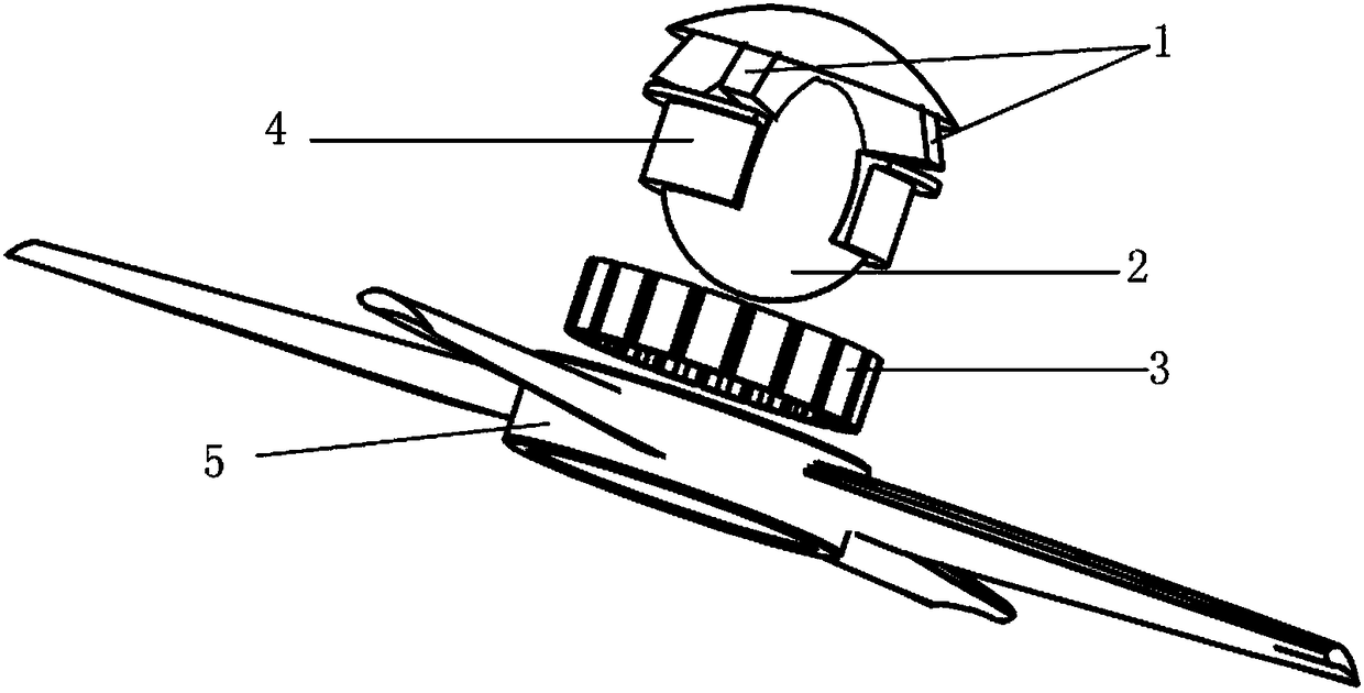
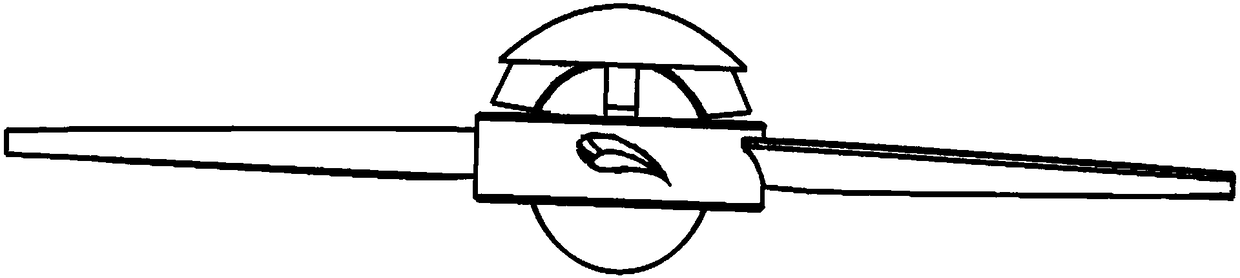
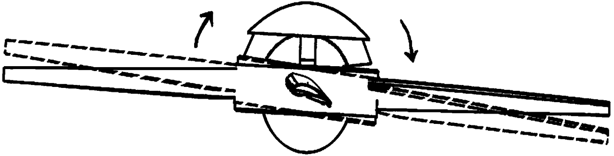
[0012] Full electromagnetic levitation magnetron rotor system, including variable magnetic controller 1, rotor ball head 2, stator magnetic coil 3, inner curved ring type stator 4 and rotor rotor fusion body 5; stator magnetic coil 3 is fixed to inner curved ring type stator 4 Outer ring, the rotor rotor fusion body 5 is set on the outer ring of the stator magnetic coil 3; the variable magnetic controller 1 is installed on the top of the rotor ball head 2, and the rotor ball head 2 is equipped with a control system for controlling the variable magnetic controller 1 The magnetic change of the inner curved ring type stator 4 is set on the rotor ball head 2. The inner curved ring type stator 4 and the rotor ball head 2 form an effective contact surface, which can rotate around the rotor ball head 2, and the inner curved ring type The top of the stator 4 ...


PUM


Abstract

A full electromagnetic suspension type magnetic control rotor system comprises variable magnetic controllers, a rotor ball, a stator magnetic coil, an inner curved surface ring stator and a rotor fusion, wherein the stator magnetic coil is fixed on the outer ring of the inner curved surface ring stator, and the outer ring of the stator magnetic coil is sleeved with the rotor fusion; the variable magnetic controllers are mounted at the top of the rotor ball, and a control system is arranged in the rotor ball and used for controlling magnetic change of the variable magnetic controllers; the rotor ball is sleeved with the inner curved surface ring stator. The system is simple and reliable on the whole, and mechanical friction among structures is effectively reduced; when a rotor rotates to produce lift force, repulsive force of a variable magnetic part can be changed, so that a rotor disc swings around the rotor ball in a controllable range, and pitching and roll control of a rotor craftis realized; the full electromagnetic suspension type magnetic control rotor system adopts simple and reliable principles and has more concise and higher efficiency as compared with a main rotor system of a helicopter.

Description

technical field [0001] The invention relates to the technical field of control of a rotor unmanned helicopter power system, in particular to a full electromagnetic levitation magnetically controlled rotor system. Background technique [0002] Today, with the rapid development of drones, its application has penetrated into various fields. The control of the power system, throttle response, and rotor attitude of the electric rotor unmanned helicopter has been affected by traditional mechanical control. Limited by the storage capacity of the battery, it is required that the energy consumption loss should be as small as possible when the electric energy is converted into lift, so as to improve the endurance of the aircraft; when there is a new breakthrough in the battery energy storage technology, it will lay the foundation for the development of the electric rotor unmanned helicopter. Existing technical problems: 1. Regarding the throttle response of the rotor unmanned helicop...

Claims


Application Information

Patent Timeline
IPC IPC(8): B64C27/32B64C27/04B64C19/00
CPCB64C19/00B64C27/04B64C27/32B64U10/10
Inventor 李支强
Owner AVIC GUIZHOU AIRPLANE
Why Eureka
Try Eureka