Enigne-driven work machine

a work machine and engine technology, applied in the direction of electrical control, agriculture tools and machines, agriculture, etc., can solve the problems of engine speed remaining high, engine output is too low to handle load, and operator's difficulty in moving the throttle lever, so as to improve the ease of operation and the working efficiency of the engine-driven work machine, finely adjust the target engine speed, and easily adjust the engine speed

Active Publication Date: 2010-06-29
HONDA MOTOR CO LTD
View PDF15 Cites 19 Cited by
  • Summary
  • Abstract
  • Description
  • Claims
  • Application Information

AI Technical Summary

Benefits of technology

[0019]An operator can therefore select a single arbitrary target engine speed from among a plurality of target engine speeds that is set in stepwise fashion, and specify the selected single target engine speed to the control unit from the target engine speed selection unit by operating the target engine speed selection unit. The control unit electrically controls the opening and closing of the throttle valve so that the actual engine speed (actual RPM) conforms to the specified target engine speed. For example, the control unit automatically controls the angle of the throttle valve via a control motor. Accordingly, the operator can shift to the target engine speed of the selected value with extreme convenience merely by operating the target engine speed selection unit. There is therefore no need for the operator to operate a throttle lever and to finely adjust the target engine speed.
[0020]For example, even when the load placed on the engine varies significantly due to significant variation of the load on the implement, the operator can easily adjust the engine speed according to the load on the engine. It is therefore possible to increase the ease of operation and the working efficiency of the engine-driven work machine.
[0021]When the load is small, engine noise can be reduced by operating the target engine speed selection unit to reduce the engine speed. As a result, the amount of noise generated by the engine-driven work machine can be further reduced, and the work environment can be further improved. By reducing the engine speed when the load is small, the fuel consumption of the engine can be reduced, and the amount of dust generated by the implement during operation can also be reduced.
[0025]Preferably, the control unit increases the specified target engine speed in stepwise fashion with increased angle of the throttle valve.

Problems solved by technology

However, it is troublesome for the operator to move the throttle lever and adjust the engine speed to the proper value each time the load on the engine changes during work.
When the engine speed is reduced to an excessive degree, the output of the engine becomes too low to handle the load.
However, when such a configuration is adopted, the engine speed remains high even when the load is small.
As a result, the noise created by the engine during high-speed rotation continues, which is disadvantageous for improving the work environment.
This configuration is also disadvantageous with regard to reducing fuel consumption by the engine.

Method used


Image

  • Enigne-driven work machine
  • Enigne-driven work machine
  • Enigne-driven work machine

Examples


first embodiment

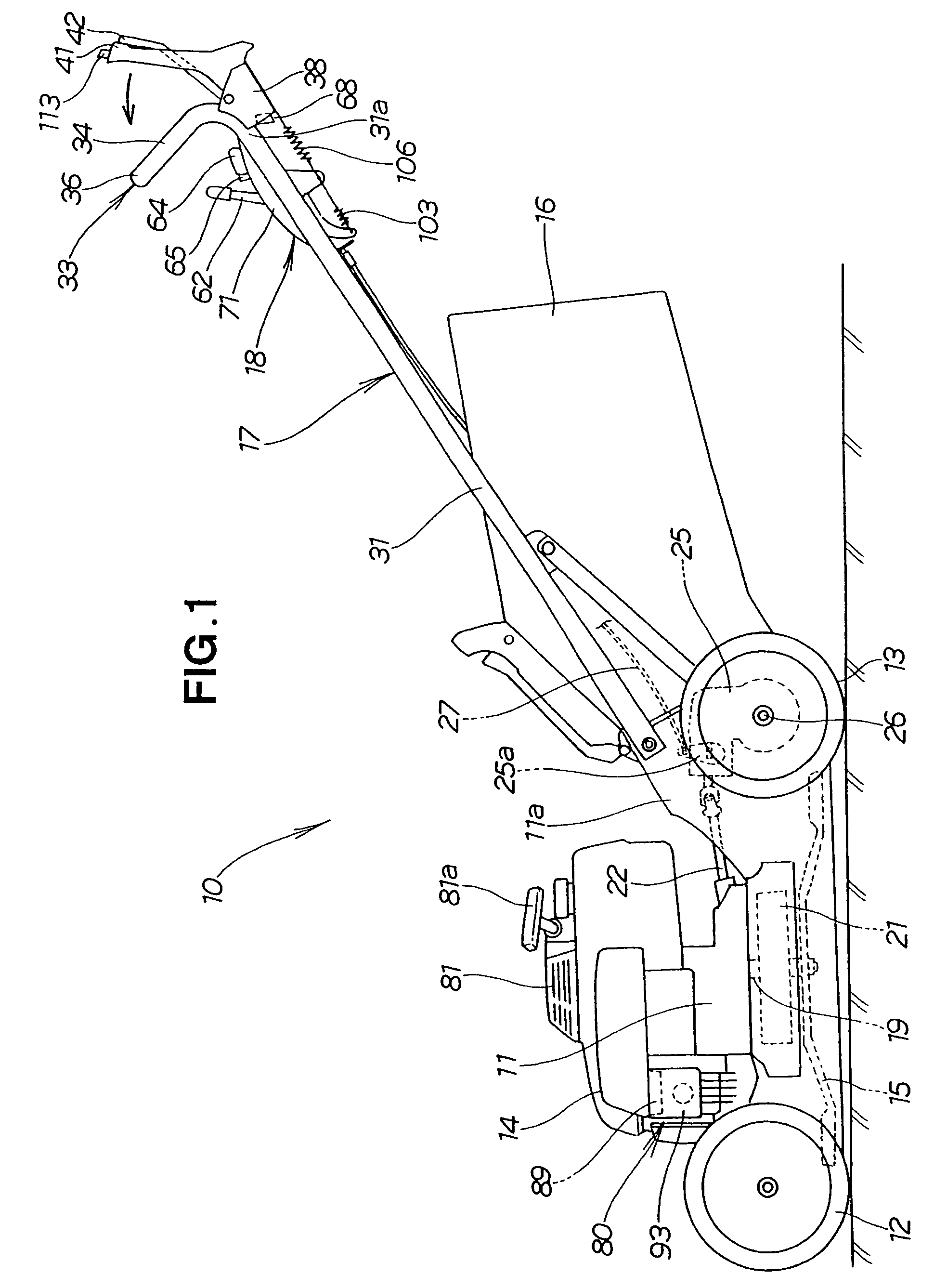
[0091]A first embodiment will now be described, based on FIGS. 1 through 11C, and using a walk-behind lawnmower as an example of an engine-driven work machine according to the present invention.

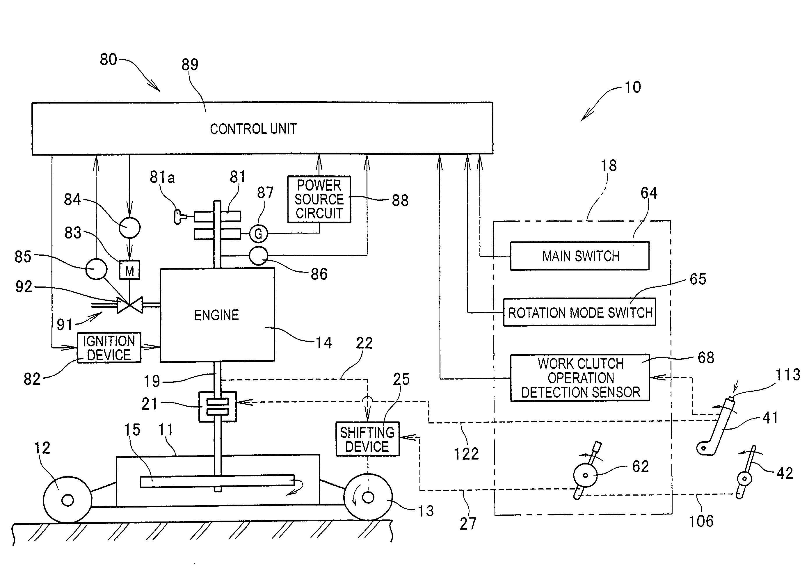
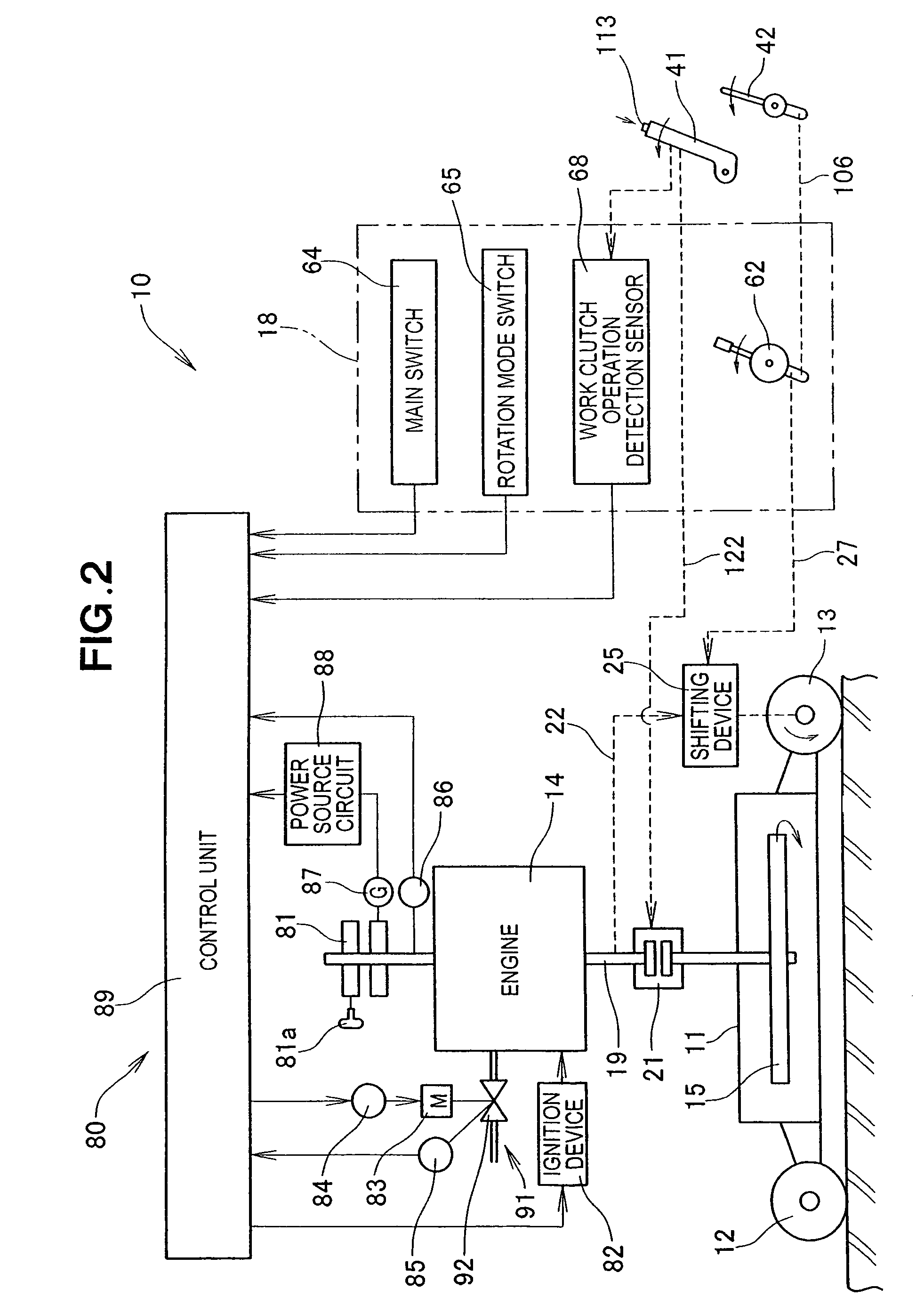
[0092]FIG. 1 shows the structure of the walk-behind lawnmower 10 of the first embodiment as viewed from the left side. The walk-behind lawnmower 10 of the first embodiment is a type of engine-driven work machine that is steered by a walking operator using a handle 17, and is (is self-propelled) by the output of an engine 14. The walk-behind lawnmower 10 is composed of a housing 11 whose lower surface is open, left and right front wheels 12, left and right rear wheels 13, an engine 14, a cutter 15, a handle 17, an operating unit 18, a work brake / clutch unit 21, and a travel shifting device 25.

[0093]The housing 11 is provided with the left and right front wheels 12, the left and right rear wheels (drive wheels) 13, the engine 14, and other main components, and therefore also functions as the ma...

second embodiment

[0205]The engine 14 of the second embodiment is mounted on the upper portion of a casing 201, and is a power source having an output shaft 19 that extends downward from the lower end portion of the engine 14.

[0206]As described above, the casing 201 is provided with the engine 14, a power transmission mechanism 203, the first and second tilling plates 205, 206, the resistance rod 207, and other main components, and therefore also functions as the machine body (frame) of the walking-type tiller 200. The casing 201 will be referred to hereinafter as the “machine body 201”, or “frame 201” as appropriate.

[0207]A clutch 202 disengages and engages the output transmitted from the engine 14 to the first and second tilling plates 205, 206. The power transmission mechanism 203 is connected to the output shaft 19 of the engine 14 in the casing 201 via the clutch 202, and is composed of a transmission shaft 211 and a bevel gear mechanism 212 for transmitting the output of the engine 14 to the ti...

third embodiment

[0230]The control modes whereby the control unit 89 of the third embodiment controls the speed of the engine 14 are broadly classified into two rotation control modes. These rotation control modes are defined as described below.

[0231]The first rotation control mode is an “idle mode” for controlling the engine speed so as to obtain the engine speed of an idling state. The second rotation control mode is a “work mode” in which the work clutch lever 41 is operated to engage the clutch 21 (clutch on), whereby control is performed to obtain the engine speed of a state in which work is performed using the torque generated by the engine 14.

[0232]The concept of control whereby the control unit 89 controls the speed of the engine 14 according to the work mode will next be described based on FIG. 18.

[0233]FIG. 18 is a conceptual diagram of the control performed by the control unit of the third embodiment, wherein the horizontal axis indicates the throttle valve angle Thr (deg.), and the verti...


PUM


Abstract

An engine-driven work machine having a target engine speed selection unit and a control unit. The target engine speed selection unit selects and specifies an arbitrary target engine speed from among a plurality of target engine speeds that is set in stepwise fashion. The control unit electrically controls the opening and closing of a throttle valve so that the actual engine speed conforms to the specified target engine speed.

Description

CROSS-REFERENCE TO RELATED APPLICATIONS[0001]The present application claims priority under 35 USC 119 based on Japanese patent applications 2006-0172922, 2006-0172389, 2006-0172434, 2006-0172498, and 2006-0172612, each of which was respectively filed Jan. 26, 2006. The subject matter of each of these priority documents, including specification, claims, and drawings, is incorporated by reference herein.FIELD OF THE INVENTION[0002]The present invention relates to an engine-driven work machine that is driven by an engine and provided with various types of implements.BACKGROUND OF THE INVENTION[0003]Work machines provided with an engine-driven implement include, for example, a work machine in which the load applied to the implement increases according to work conditions, such as in a walk-behind lawnmower. A walk-behind lawnmower is a work machine that cuts grass using a cutter while under self-propulsion, and that is controlled by a walking operator. This type of walk-behind lawnmower ...

Claims


Application Information

Patent Timeline
Patent Type & Authority Patents(United States)
IPC IPC(8): B60W10/06
CPCA01D34/67F02D9/02F02D11/02F02D11/10F02D31/002F02D41/021F02B63/02Y10T477/79F02D2011/102F02D2400/06Y02T10/14Y10T477/70Y10T477/675Y02T10/12A01D34/68
Inventor KOBAYASHI, HIROSHISASAOKA, MASAYUKIINOUE, TOSHIOSHIMADA, KENZOMAEKAWA, YOSHINORI
Owner HONDA MOTOR CO LTD
Why Eureka
Try Eureka