

A method for reforming the main assembly jig of a car body
A body and fixture technology, which is applied in the field of car body main assembly fixture transformation, can solve the problems of rapid transformation without body body main assembly fixture, etc., and achieve the effect of fast transformation speed, improved production cycle and efficiency, and high transformation quality
Active Publication Date: 2022-06-10
CHANGSHA CTR ROBOTICS
View PDF13 Cites 0 Cited by
- Summary
- Abstract
- Description
- Claims
- Application Information
AI Technical Summary
Problems solved by technology
[0006] However, in the prior art, there is no method for quickly transforming the body main fixture
Method used
View moreImage
Smart ImageViewing Examples

Examples
Embodiment Construction
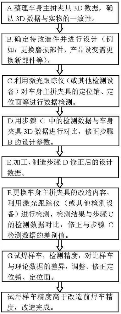
[0035] After the transformation is completed, the precision of the test welding sample car is higher than the precision of the welding car before the transformation.
[0038] The positioning portion is a positioning pin and a positioning surface.
Login to View More PUM
 Abstract
The invention discloses a method for transforming the main assembly fixture of a vehicle body, comprising: A, obtaining the original 3D data corresponding to the main assembly fixture of the vehicle body to be modified; B, determining the part to be modified and designing its coordinate value A2; C, performing data processing on the positioning part Get the first detection data; D, compare the first detection data with the original 3D data, and correct the coordinate value A2 to the first detection data; E, process and manufacture the part to be modified according to the corrected coordinate value; F, replace the to-be-reformed The part is a new part; the data detection of the positioning part is carried out to obtain the second detection data; the second detection data is compared with the first detection data, and the number of gaskets at the part to be modified is adjusted; G, try welding the prototype car and test the accuracy of the body, Determine whether the actual accuracy of the body reaches the theoretical accuracy, if not, adjust the number of shims at the part to be rebuilt and repeat step G; if so, the remodeling process ends. The invention has fast transformation speed and high quality; improves the production tempo and efficiency of the whole welding assembly line, and improves the welding and manufacturing quality of the body-in-white.
Description
A method for transforming the main assembly jig of a car body technical field [0001] The present invention particularly relates to a method for transforming a main body assembly fixture. Background technique [0002] The Chinese utility model patent with the application number of 201120570974.5 discloses a body-in-white assembly main welding The positive effect of the new central clamp is that the external welding space is large, the operation accessibility is good, and each positioning and clamping unit has self-locking function. It can ensure the quality of the whole vehicle, and make full use of the space in the air to switch between different models, which is suitable for the production requirements of multiple models. The utility model The structural form of each positioning and clamping unit is described in the patent. However, after a period of use, each positioning and clamping unit is There will be a certain amount of wear and tear, and the precision will de...
Claims
Login to View More Application Information
Patent Timeline
 Patent Type & AuthorityPatents(China)
IPC IPC(8): G05B19/4097B23K37/04
CPCG05B19/4097B23K37/04B23K2101/006G05B2219/32153Y02P90/02
Inventor唐源波高狄甘超梁施华向健淋王勇军
OwnerCHANGSHA CTR ROBOTICS