Eureka AIR delivers breakthrough ideas for toughest innovation challenges, trusted by R&D personnel around the world.

Vehicle abnormal deceleration region detecting method and system based on trajectory data

A technology of trajectory data and area detection, applied in the field of intelligent transportation, can solve the problems of low inspection efficiency and high delay

Active Publication Date: 2019-10-25
ENJOYOR COMPANY LIMITED
View PDF15 Cites 12 Cited by
  • Summary
  • Abstract
  • Description
  • Claims
  • Application Information

AI Technical Summary

Problems solved by technology

The invention overcomes the problems of low efficiency and high delay in traditional road network traffic event inspection

Method used


Image

  • Vehicle abnormal deceleration region detecting method and system based on trajectory data
  • Vehicle abnormal deceleration region detecting method and system based on trajectory data
  • Vehicle abnormal deceleration region detecting method and system based on trajectory data

Examples


Embodiment 1

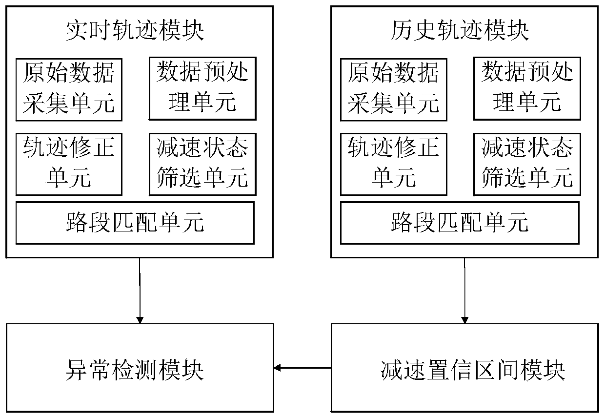
[0082] Embodiment 1: as figure 1 As shown, a vehicle abnormal deceleration area detection system based on trajectory data includes a real-time trajectory module, a historical trajectory module, a deceleration confidence interval module, and an abnormality detection module; wherein, the real-time trajectory module and the historical trajectory module include raw data Acquisition unit, data preprocessing unit, trajectory correction unit, deceleration status screening unit, road section matching unit; the real-time trajectory module is connected to the abnormal detection module; the historical trajectory module is connected to the deceleration confidence interval module; the deceleration The confidence interval module is connected to the anomaly detection module.

[0083] A method for detecting an abnormal deceleration area of ​​a vehicle based on trajectory data, the specific steps are:

[0084] S1. Obtain the original trajectory data of the vehicle and the geographical informa...

Embodiment 2

[0186] Embodiment 2: A method for detecting an abnormal deceleration region of a vehicle based on trajectory data, the specific steps are:

[0187] S1. Obtaining the original trajectory data of the vehicle and the geographical information data of the urban road network;

[0188] S2. Carry out map matching on the trajectory data, and identify the driving state of the vehicle.

[0189] S3. Screen the historical trajectory points in the deceleration state, and use a clustering algorithm to construct a deceleration confidence area.

[0190] S3.1. Obtain the matching results of all vehicle historical trajectory data, and filter deceleration points.

[0191] S3.2. Use the density-based clustering method to cluster the deceleration points and construct a historical deceleration confidence area. Density-based clustering methods include, but are not limited to: DBSCAN algorithm, SNN (shared nearest neighbor) algorithm, density peak-based algorithm DP (Clustering by fast search and fi...


PUM


Abstract

The invention relates to a vehicle abnormal deceleration region detecting method and a vehicle abnormal deceleration region detecting system based on trajectory data. The vehicle abnormal decelerationregion detecting method refers to an image differential anomaly detection method commonly used in machine vision, performs analysis and clustering on historical trajectory data, constructs an ''imagebackground'' of a road section deceleration region, compares a deceleration confidence region with a deceleration region based on real-time data clustering, and highlighting an abnormal decelerationregion of the road section. The vehicle abnormal deceleration region detecting method and the vehicle abnormal deceleration region detecting system overcome the problems of low patrol efficiency and high delay of the traditional road network traffic events, can provide data support for the traffic department to maintain normal operation of the traffic system, shorten the discovery time of the roadabnormal event, reduce the labor cost, can push anomaly information to drivers near the abnormal deceleration region by means of communication software, realize the timely induction of vehicles and avoid the occurrence of large-scale congestion.

Description

technical field [0001] The invention relates to the field of intelligent transportation, in particular to a method and system for detecting abnormal deceleration areas of vehicles based on track data. Background technique [0002] With the construction of Intelligent Transportation System (ITS) and the development of information technology, it is possible to obtain real-time vehicle GPS trajectory data and carry out data mining. Vehicle trajectory data can provide rich traffic data, such as vehicle location, driving speed, queue length, etc. Therefore, it is very helpful for the discovery and timely processing of abnormal road traffic events. [0003] At this stage, traffic accidents, illegal driving, road damage and other events that affect the normal driving of vehicles can usually only be confirmed manually by people's telephone complaints and police on-site patrols. The traffic control department needs to spend a lot of manpower and material resources to maintain the s...

Claims


Application Information

Patent Timeline
IPC IPC(8): G08G1/01G08G1/052G06K9/62
CPCG08G1/0137G08G1/052G06F18/22G06F18/23
Inventor 谢竞成吴越徐甲丁楚吟邹开荣袁鑫良金峻臣李瑶周浩敏
Owner ENJOYOR COMPANY LIMITED
Why Eureka
Eureka Blog
Learn More