A quick-connect high-voltage switchgear

A high-voltage switchgear and quick-connect technology, which is applied to the parts of the connection device, the connection/disconnection of the connection device, and the connection, etc., can solve the problems affecting the normal use of the switchgear system and the long power outage time, so as to avoid long-term interruptions. The electrical and lap joint process is fast and the effect of improving the connection effect

Active Publication Date: 2020-09-15
SHANDONG GUANGYUN INTELLIGENT TECH CO LTD
View PDF4 Cites 0 Cited by
  • Summary
  • Abstract
  • Description
  • Claims
  • Application Information

AI Technical Summary

Problems solved by technology

Except the handcart switch (circuit breaker mechanism) of this switchgear can be moved and pulled out for inspection, other accessories are fixed. Since the connection between the high-voltage busbar and the incoming copper bar is a live connection, if the normal annual inspection or fault inspection is performed, it will be guaranteed When the maintenance personnel are safe, the compulsory power outage takes a long time (about 8 hours), and the power outage time is longer if there are no accessories, which greatly affects the normal use of the switchgear system

Method used


Image

  • A quick-connect high-voltage switchgear
  • A quick-connect high-voltage switchgear
  • A quick-connect high-voltage switchgear

Examples


Embodiment 1

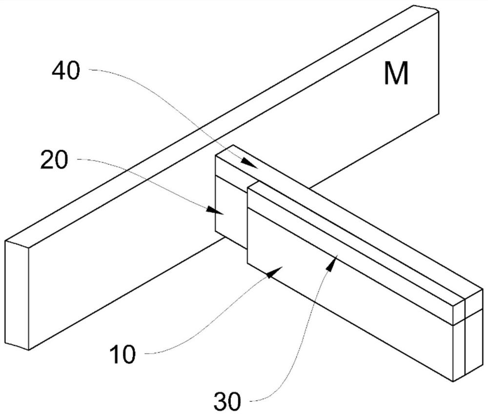
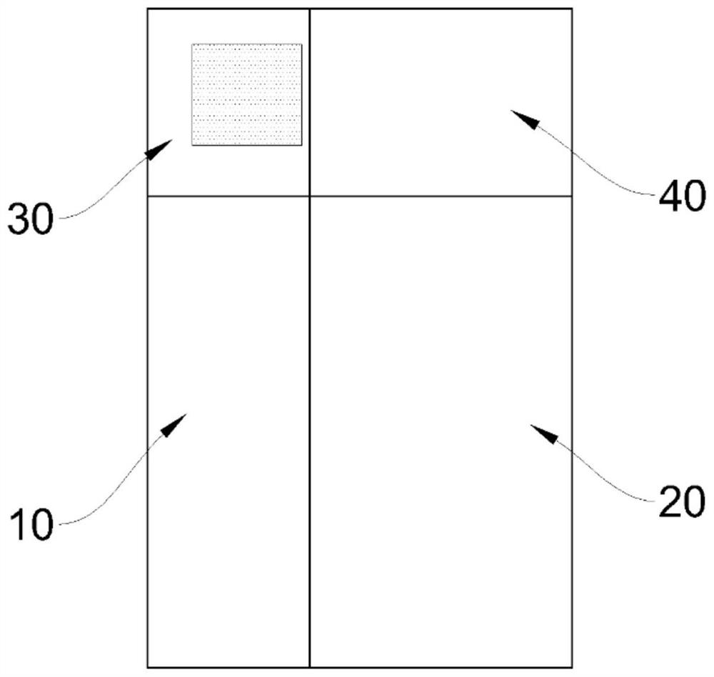
[0030] Such as Figure 1-Figure 2 As shown, a quick-connect high-voltage switchgear, the incoming copper bar 10 of the high-voltage switchgear and the busbar copper bar 20 are fixedly overlapped, and the busbar copper bar 20 is led out from the main busbar M and has a "T" shape structure , the upper side of the incoming line copper bar 10 is fixedly connected with an adsorption part 30, and the upper side of the corresponding busbar copper bar 20 is fixedly connected with an adsorption plate 40; the adsorption part 30 is an electromagnetic adsorption device with an electromagnet inside and is set There is a circuit channel for the power supply line to pass through; the adsorption surface of the adsorption part 30 and the adsorption plate 40 is parallel to the overlapping surface of the incoming copper bar 10 and the busbar copper bar 20 on the same plane.

[0031] The overall connection process of the high-voltage switchgear in this embodiment is as follows: move the high-volt...

Embodiment 2

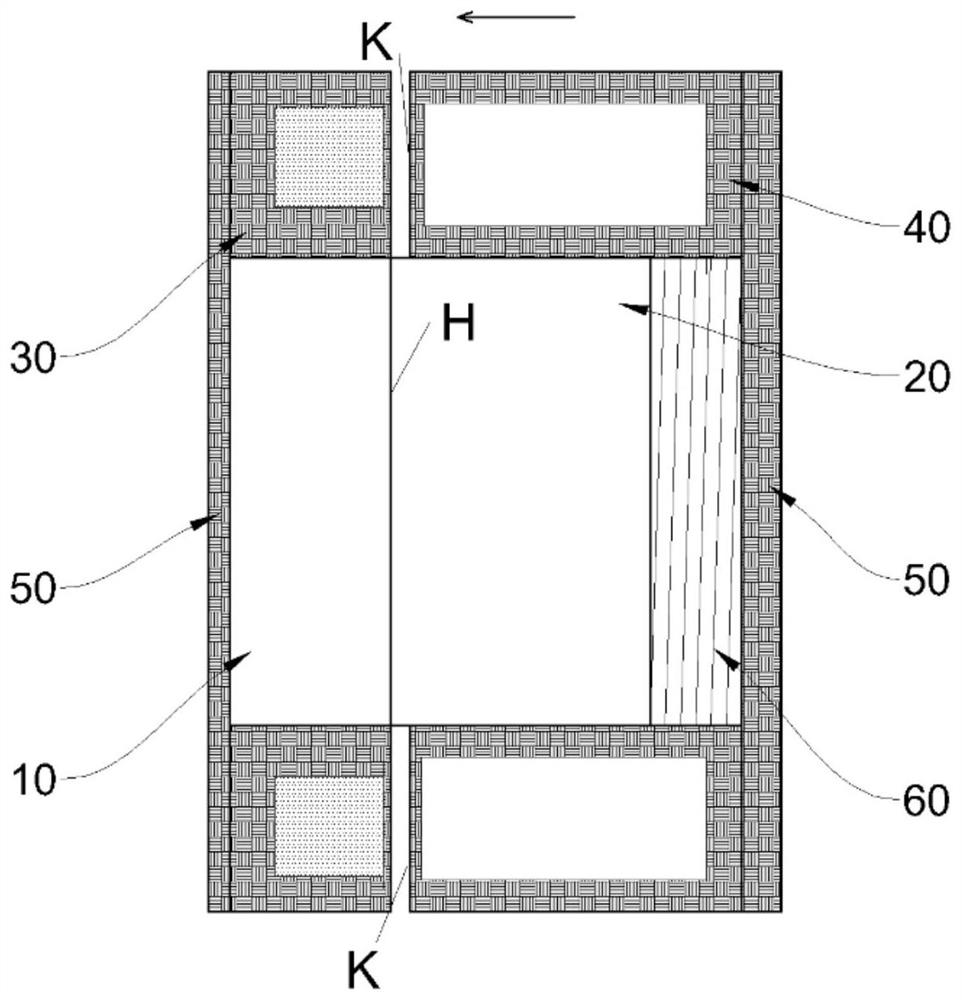
[0036] Such as image 3 As shown, this embodiment is optimized as follows on the basis of Embodiment 1: the adsorption part 30 and the adsorption plate 40 are respectively fixed on the upper and lower sides of the incoming copper bar 10 and the bus bar 20; The adsorption part 30 and the two adsorption plates 40 are respectively fixedly connected by the connecting bridge 50 located on the opposite surface of the overlapping surface H. Concave" shape. Further setting: the connecting bridge 50 of the two adsorption plates 40 is fixedly connected to the busbar copper bar 20 through the pressure spring 60, the two adsorption plates 40 are slidably arranged on both sides of the bus bar copper bar 20, and the adsorption surfaces K of the two adsorption plates 40 are located at The outer side of the overlapping surface H.

[0037] The connection process of the busbar copper bar 20 and the incoming line copper bar 10 in this embodiment is as follows: the electromagnetic adsorption de...

Embodiment 3

[0041] Such as Figure 4 As shown, this embodiment is optimized as follows on the basis of Embodiment 2: the high-voltage switchgear also includes a signal activation device 70, and the signal activation device 70 includes a baffle vertically arranged outside the front end of the incoming copper bar 10 71 and block 72; the block 72 is an "L" shape with the same length of the two arms, and is hingedly arranged on the support plate 73 fixedly connected with the cabinet through a bending point; the baffle 71 follows the incoming line When the copper bar 10 moves or moves away from the end, it touches the inner surface of the stopper 72 to make it turn over. The support plate 73 is respectively provided with a pressure sensor 74 at the pressing part of the outer side of the stopper 72 after turning over.

[0042] Through the above-mentioned settings of this embodiment, the position of the incoming copper bar 10 is positioned and the electromagnetic adsorption device is turned on b...


PUM


Abstract

The present invention relates to the technical field of high-voltage switch cabinets, and specifically discloses a high-voltage switch cabinet that may quickly achieve connection between a copper busbar and an incoming line copper bar while electrified, which greatly reduces the power-off time when carrying out fault maintenance or annual inspections on the high-voltage switch cabinet, and increases the working efficiency. Specifically: the incoming line copper bar and the copper busbar of the high-voltage switch cabinet are fixed and in lap-joint connection, the copper busbar is drawn out from a main busbar and forms a T-shaped structure therewith, an absorption part is fixedly connected to at least one side surface of the incoming line copper bar, and an absorption plate is fixedly connected to a corresponding copper busbar side surface; the absorption part is an electromagnetic absorption apparatus that is internally provided with an electromagnet and is provided with a circuit channel for an electrical wire to pass through; the absorption part, the absorption surface of the absorption plate, and the lap-joint surface of the incoming line copper bar and the copper busbar are parallel on the same plane.

Description

technical field [0001] The invention relates to the technical field of switchgear, in particular to a high-voltage switchgear capable of quick connection under electrified conditions, shortening the system power-off time during fault maintenance of the switchgear, and improving work efficiency. Background technique [0002] In the power system, 10kV high-voltage switchgear is widely used. Among them, KYN28A-12 metal armored removable switchgear is widely used in power systems. KYN28A-12 switchgear consists of a fixed cabinet and a removable vacuum circuit breaker handcart. The fixed switch cabinet is divided into four small rooms: busbar room, circuit breaker room, cable room and low-voltage room. The basic cabinet types of switch cabinets are incoming cabinets and feeder cabinets. In addition to the basic cabinet type, there are other derivative schemes, such as bus section cabinets, metering cabinets, PT cabinets, and variable cabinets used. In addition, there are also ...

Claims


Application Information

Patent Timeline
Patent Type & Authority Patents(China)
IPC IPC(8): H01R13/62H01R13/66H01R43/26H02B3/00H02G5/02
CPCH01R13/6205H01R13/6633H01R13/6683H01R43/26H02B3/00H02G5/02
Inventor 张敬敏许同春周广红
Owner SHANDONG GUANGYUN INTELLIGENT TECH CO LTD
Why Eureka
Try Eureka