

Power conversion device and control method of power conversion device
A technology of power conversion device and control method, which is applied in the direction of output power conversion device, conversion of AC power input to DC power output, electrical components, etc., which can solve the problems of high cost, increased inverter operating cost, and increased switching loss And other issues
- Summary
- Abstract
- Description
- Claims
- Application Information
AI Technical Summary
Problems solved by technology
Method used
Image

Examples
no. 1 Embodiment approach
[0031] First, the first embodiment will be described. Hereinafter, the description of the parts common to the above-mentioned conventional configuration will be omitted, and the description will focus on the different parts.
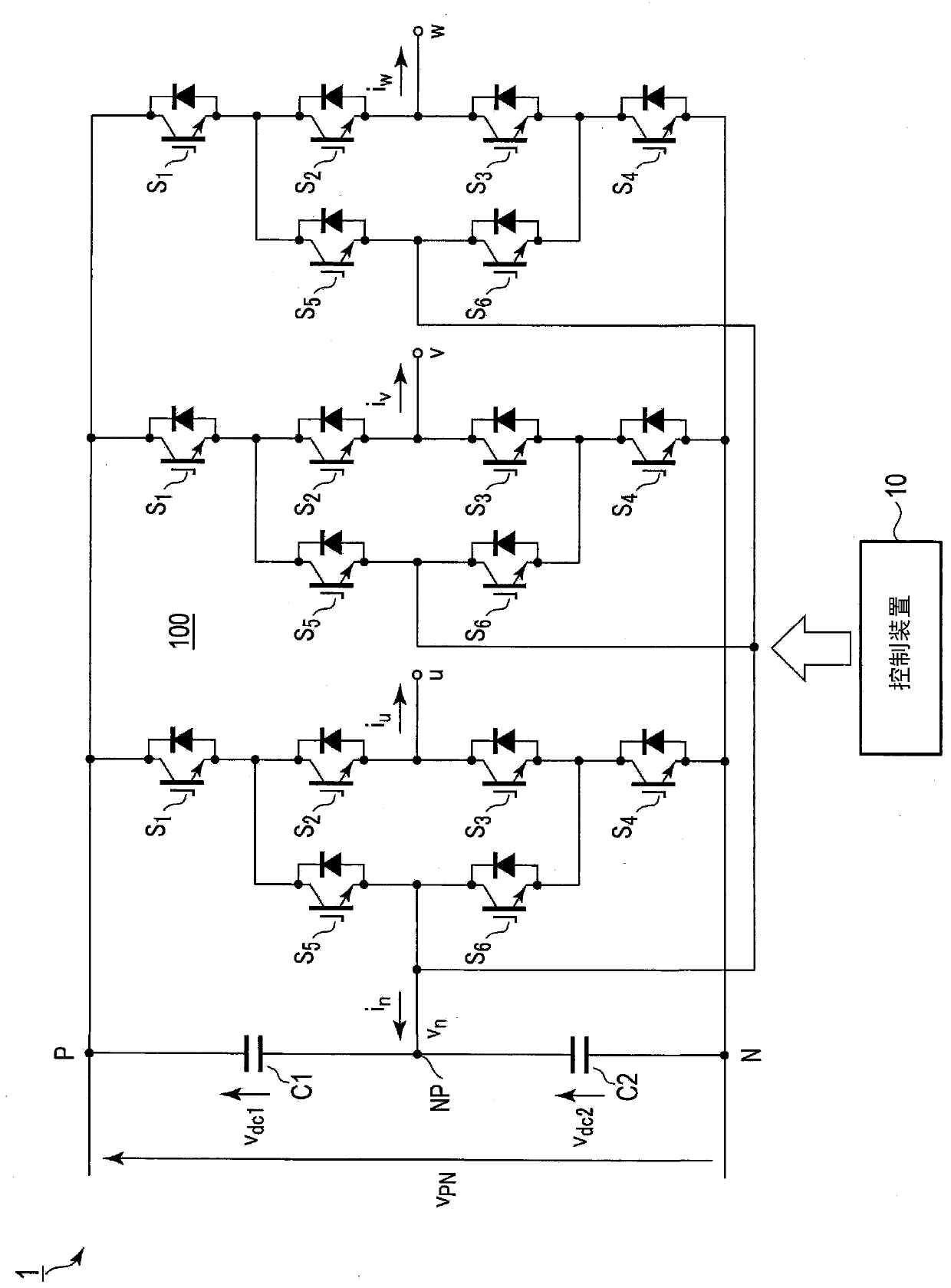
[0032] figure 1 It is a figure which shows an example of the structure of the power conversion apparatus of 1st Embodiment. Additionally, in the figure 1 , against the above Figure 7 Common elements are assigned the same reference numerals.
[0033] The NPC inverter 100 constituting the power conversion device 1 is Figure 7Shown is the same usual three-phase NPC inverter. However, it is not limited to this example. For example, in this embodiment, an NPC inverter is exemplified as a neutral point clamp type power converter, but it may be implemented by replacing it with an NPC converter. In addition, the neutral point clamp may be a T-type neutral point clamp or other types.
[0034] In this power conversion device 1, there are further function...
no. 2 Embodiment approach
[0071] Next, a second embodiment will be described. Hereinafter, the description of the parts common to the first embodiment will be omitted, and the different parts will be mainly described.
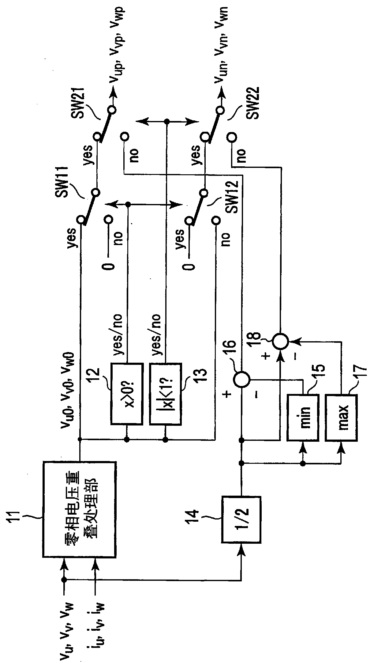
[0072] The structure and figure 1 Same as shown. However, the control device 10 of the second embodiment has the same figure 2 A judging unit (not shown) different from the judging unit 13 shown switches the control mode with a judging criterion different from that of the first embodiment.
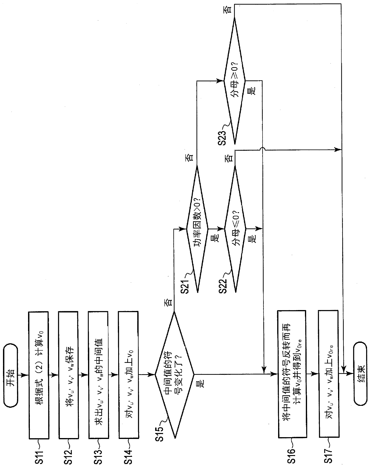
[0073] The control device 10 of the second embodiment performs switching from the second control mode to the first control mode (or switching from the first control mode to the second control mode) according to the operating conditions of the NPC inverter 100 . The operating conditions to which the first control mode is applied or the operating conditions to which the second control mode is applied are set in advance using, for example, a modulation factor and a power factor. In addition, it i...
no. 3 Embodiment approach
[0077] Next, a third embodiment will be described. Hereinafter, the description of the parts common to the first embodiment will be omitted, and the description will focus on the different parts.
[0078] The configuration of the power conversion device according to the third embodiment and figure 1 Same as shown. However, the control device 10 of the third embodiment also has the function of, in the second control mode, according to the upper arm voltage command value v up and the voltage command value v for the lower branch un Each state changes the carrier frequency of the NPC inverter 100 .
[0079] For example, the control device 10 has the function of using the voltage command value v in the upper branch up and the voltage command value v for the lower branch un When the two are not 0, the carrier frequency is reduced to, for example, the usual 1 / 2 frequency, or the semiconductor switching element S of the upper branch 1 , S 2 , S 5 with the lower branch semicon...
PUM
 Abstract
Description
Claims
Application Information