ride control device

A technology of driving control and vehicle control devices, which is applied in the direction of control devices, traffic control systems, road vehicle traffic control systems, etc., and can solve problems such as the lateral movement speed of wrong stationary objects

Active Publication Date: 2017-11-17
HONDA MOTOR CO LTD
View PDF1 Cites 0 Cited by
  • Summary
  • Abstract
  • Description
  • Claims
  • Application Information

AI Technical Summary

Problems solved by technology

[0003] With the above-mentioned driving control device related to the prior art, since the detection range also moves when the vehicle moves, at the left end or right end of the detection range, a part of the object is outside the detection range, and the size and center of gravity of the detected object will change. changes, and thus sometimes falsely detects that stationary objects also have lateral velocity

Method used


Image

  • ride control device
  • ride control device
  • ride control device

Examples


Embodiment Construction

[0019] Next, a travel control device according to an embodiment of the present invention will be described with reference to the drawings.

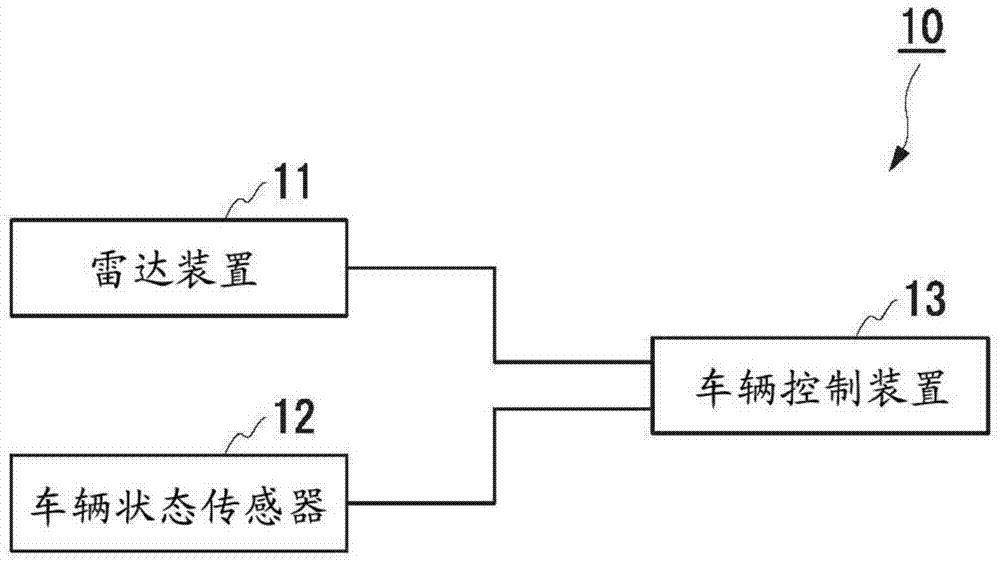
[0020] Such as figure 1 As shown, the travel control device 10 according to this embodiment includes a radar device 11 (detection device), a vehicle state sensor 12, and a vehicle control device 13. The travel control device 10 is mounted on the vehicle 1. As shown in FIG.

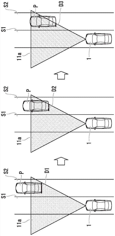
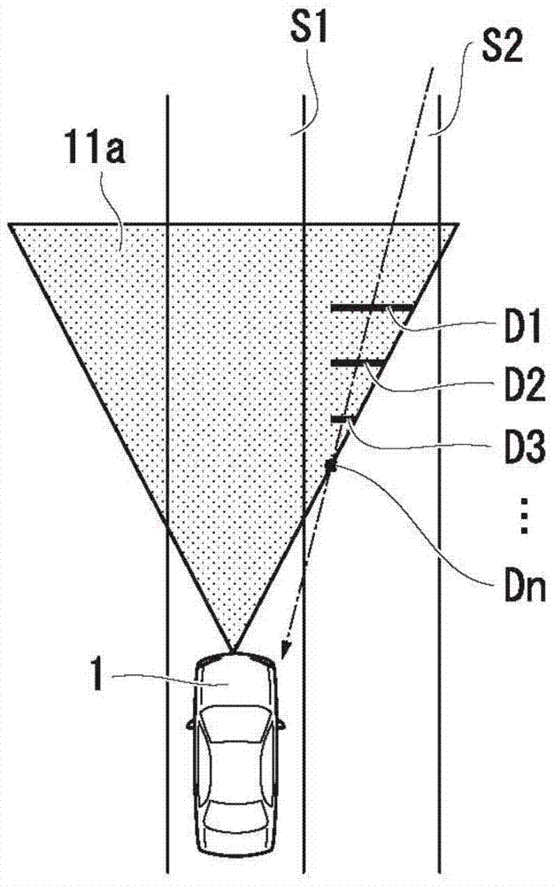
[0021] The radar device 11 divides a detection range 11a set outside the vehicle 1 into a plurality of angular areas, emits electromagnetic waves as transmission signals, and scans each angular area. In addition, the radar device 11 receives reflection signals generated by reflection of each transmission signal by objects outside the vehicle 1 (for example, pedestrians, other vehicles (second vehicles), various stationary objects on or above the road surface, etc.) Wave. The radar device 11 generates a detection signal according to the transmitted signal and the re...


PUM


Abstract

A travel control apparatus includes: a detection device configured to detect an object ahead in a travel direction of a vehicle; and a vehicle control device configured to perform a vehicle control in which the object is regarded as a control reference when a lateral movement speed of the object is directed to a travel lane of the vehicle, wherein even when the lateral movement speed of the object is directed to the travel lane of the vehicle, when the object is detected in right and left ends of a detection range of the detection device, the vehicle control device prevents the vehicle control.

Description

technical field [0001] The invention relates to a driving control device. Background technique [0002] In the prior art, a driving control device is known. The driving control device detects an object through the laser radar sensor. When the predicted lateral position calculated according to the lateral moving speed of the object is within the driving lane, the object is taken In the following object, the detection area of ​​the lidar sensor is set in front of the traveling direction of the vehicle (for example, refer to Japanese Patent Laid-Open Publication No. 2000-137900). [0003] With the above-mentioned driving control device related to the prior art, since the detection range also moves when the vehicle moves, at the left end or right end of the detection range, a part of the object is outside the detection range, and the size and center of gravity of the detected object will change. changes, and thus sometimes falsely detects that stationary objects also have later...

Claims


Application Information

Patent Timeline
Patent Type & Authority Patents(China)
IPC IPC(8): B60W30/095B60W50/16
CPCB60W30/095B60W50/16B60W2050/143B60W2050/146B60W2554/803B60W30/09B60W2420/52B60W2554/4041B60W2554/80G08G1/167G08G1/16
Inventor 小阪研吾
Owner HONDA MOTOR CO LTD
Why Eureka
Try Eureka