motor control unit
A control device and motor technology, applied in the direction of multiple motor speed adjustment, etc., can solve the problems that it is difficult to fully improve the control responsiveness of the servo controller, it is difficult to improve the synchronization accuracy between axes, and it is difficult to fully suppress the errors of modules and servo controllers.
- Summary
- Abstract
- Description
- Claims
- Application Information
AI Technical Summary
Problems solved by technology
Method used
Image
Examples
no. 1 approach
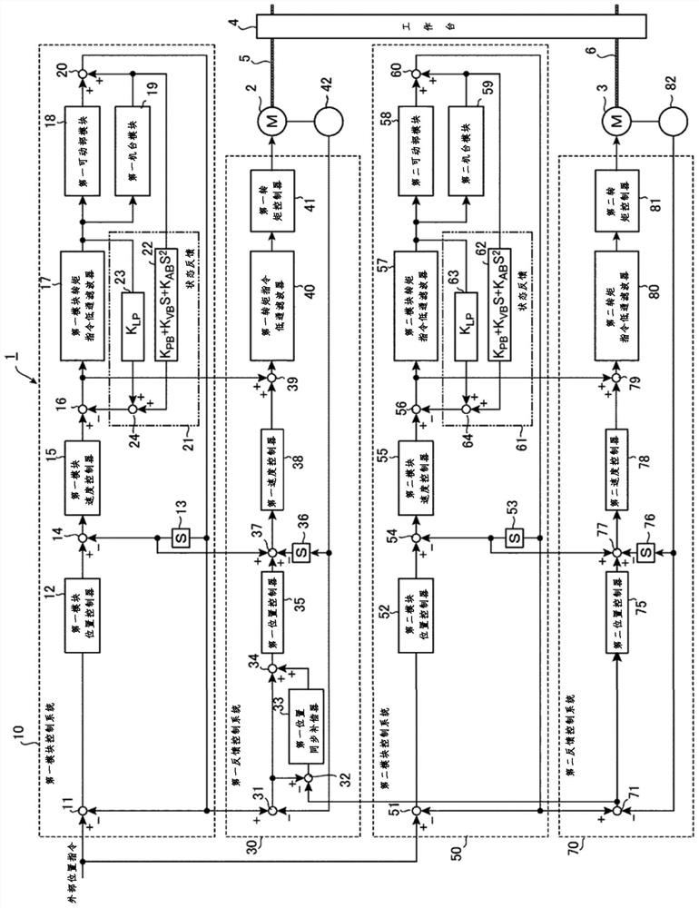
[0121] figure 1 It is a block diagram of the motor control device 1 according to the first embodiment of the present invention. figure 1 The shown motor control device 1 uses two motors, a first motor 2 and a second motor 3, to jointly drive one movable part. Thereby, the motor control device 1 can specify the position of the movable part at high speed and with high precision.
[0122] Such as figure 1 As shown, the motor control device 1 has: a first module control system 10 , a first feedback control system 30 , a second module control system 50 and a second feedback control system 70 .
[0123] An external position command indicating the control position of the table 4 as a movable part is input to the first module control system 10 . The first module control system 10 generates various first module instructions.
[0124] The first feedback control system 30 has a feedback loop including the first electric motor 2 . The first feedback control system 30 actually control...
no. 2 approach
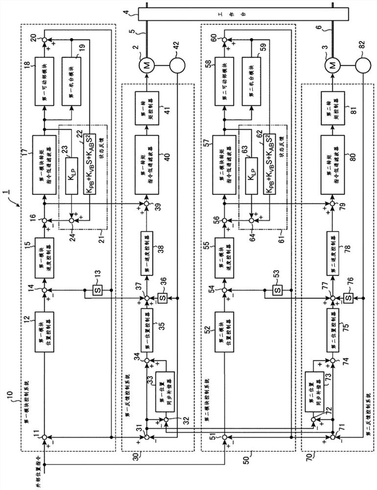
[0199] figure 2 It is a block diagram of a motor control device 1 according to a second embodiment of the present invention. figure 2 The motor control device 1 shown with figure 1 The difference between the devices shown is that the second feedback control system 70 has a second synchronous position error obtainer 72 , a second position synchronous compensator 73 and a second synchronous compensation position error obtainer 74 .
[0200] The second synchronous position error obtainer 72, the second position synchronous compensator 73 and the second synchronous compensation position error obtainer 74 correspond to the first synchronous position error obtainer 32, the first position synchronous compensator 33 and the first synchronous compensation position Error acquirer 34.
[0201] Based on the second control position error acquired by the second control position error acquirer 71 and the first control position error acquired by the first control position error acquirer 3...
no. 3 approach
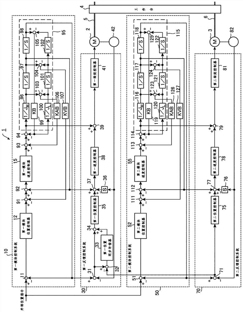
[0210] image 3 It is a block diagram of a motor control device 1 according to a third embodiment of the present invention. image 3 The motor control device 1 shown has: a first modular control system 10 , a first feedback control system 30 , a second modular control system 50 and a second feedback control system 70 . image 3 The motor control device 1 shown with figure 1 Similarly, the motor control device 1 shown uses two motors, the first motor 2 and the second motor 3, to jointly drive one movable part. Thereby, the motor control device 1 can determine the position of the movable part at high speed and with high precision.
[0211] Below, around the figure 1 Differences from the illustrated motor control device 1 will be described. Additionally, with figure 1 The same structural elements of the shown motor control device 1 are adopted as figure 1 The same reference numerals are used, and descriptions thereof are omitted.
[0212] The first feedback control system ...
PUM
 Abstract
Description
Claims
Application Information
 - R&D
- Intellectual Property
- Life Sciences
- Materials
- Tech Scout
- Unparalleled Data Quality
- Higher Quality Content
- 60% Fewer Hallucinations
Browse by: Latest US Patents, China's latest patents, Technical Efficacy Thesaurus, Application Domain, Technology Topic, Popular Technical Reports.
© 2025 PatSnap. All rights reserved.Legal|Privacy policy|Modern Slavery Act Transparency Statement|Sitemap|About US| Contact US: help@patsnap.com


