Elevator comprising an electric linear motor

A linear motor and elevator technology, which is applied to the deceleration device of the DC motor, the control of the AC motor, and the elevator in the building, etc., can solve the problems such as the undesired movement of the elevator car and the inapplicability of the elevator brake, and achieve the effect of ensuring safety.

Active Publication Date: 2019-10-25
KONE CORP
View PDF9 Cites 1 Cited by
  • Summary
  • Abstract
  • Description
  • Claims
  • Application Information

AI Technical Summary

Problems solved by technology

For this reason, the general design of elevator brakes, which is always based on the braking of the traction sheaves of the elevator car driven by the hoisting ropes, is not suitable for this concept
Furthermore, if the hoisting ropes are very long, as is the case with high-rise elevators, movement of the elevator car due to swaying or stretching of the hoisting ropes can lead to undesired movement of the elevator car

Method used


Image

  • Elevator comprising an electric linear motor
  • Elevator comprising an electric linear motor
  • Elevator comprising an electric linear motor

Examples


Embodiment Construction

[0044] It is emphasized that the same part or parts having the same function are denoted by the same reference numerals throughout the figures.

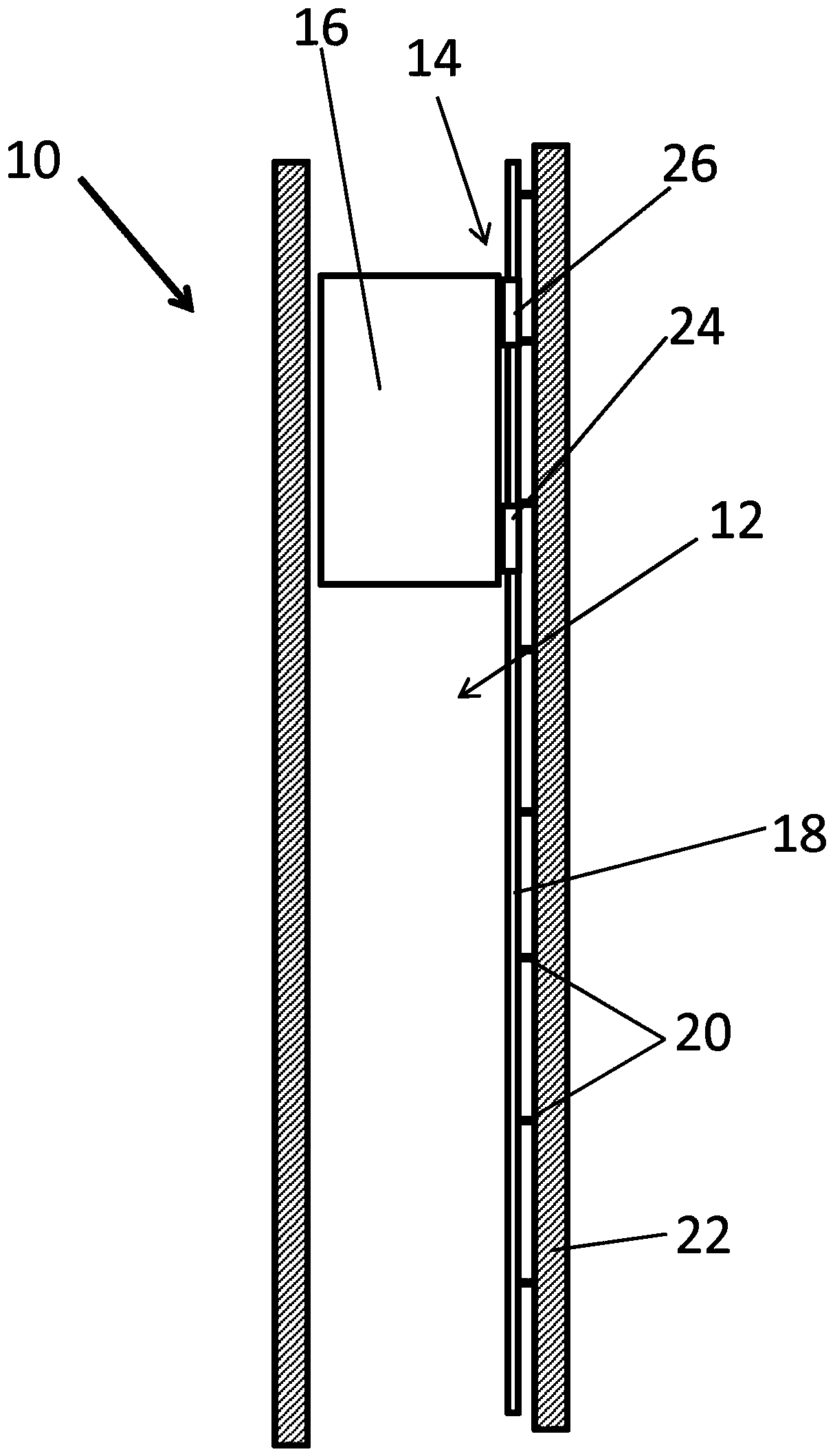
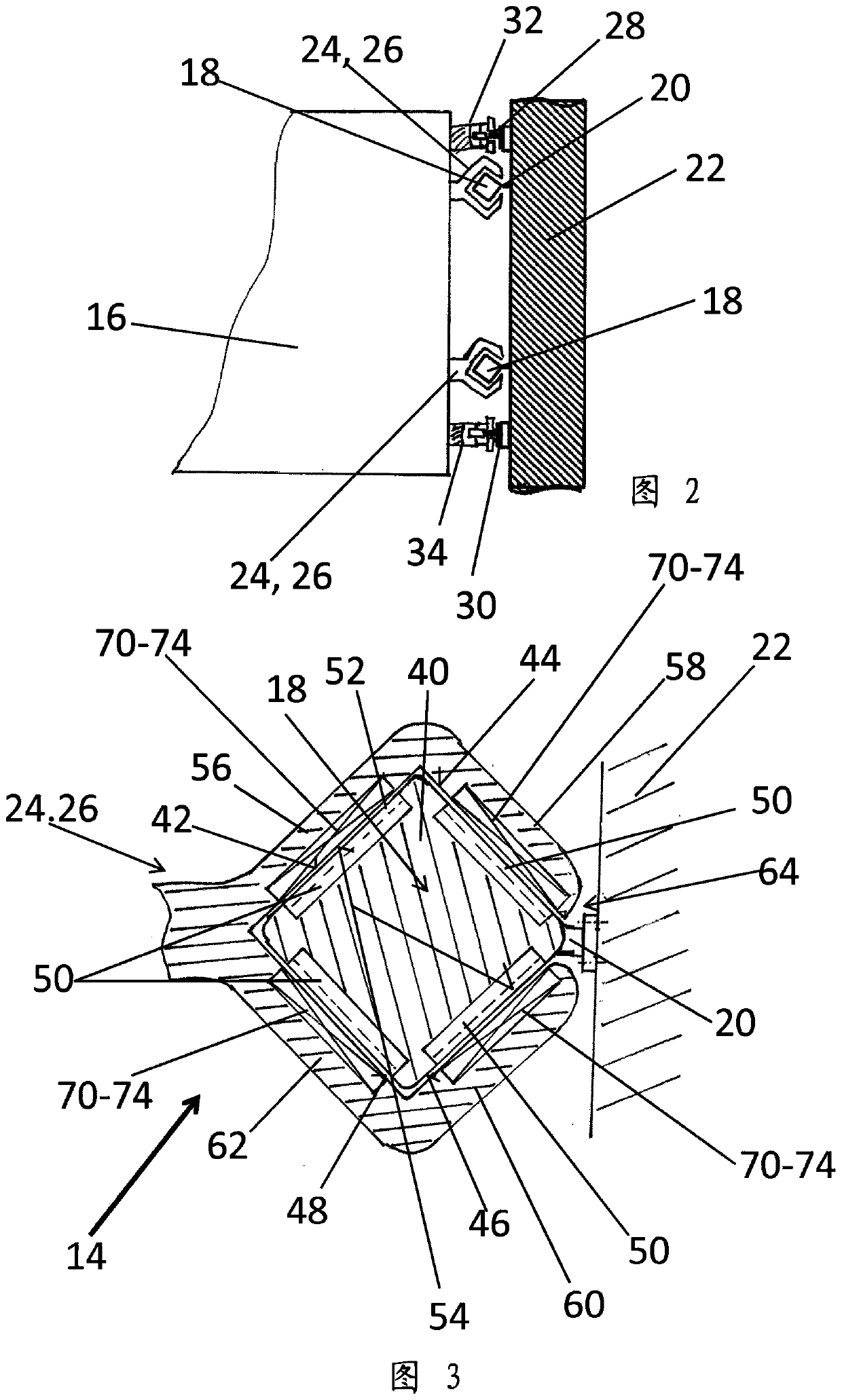
[0045] figure 1 Shown is an elevator 10 comprising an elevator shaft 12 in which an elevator car 16 moves up and down as an element to be moved along a movement path defined by two guide rails. The elevator 10 has a linear elevator motor 14 . The linear elevator motor 14 includes a stator 50 positioned in the side of the stator beam 18 (see image 3 ), the stator beam 18 is mounted to the hoistway wall 22 of the elevator hoistway 12 by means of fastening elements 20 . In this example, the elevator 10 has two parallel stator beams 18, which can be figure 2 seen in.

[0046] The elevator car 16 includes two movers 24, 26 positioned one above the other. The lower mover 24 is located in the lower half of the elevator car, while the upper mover 26 is located in the upper half of the elevator car. These two movers 24,26 include for ...


PUM


Abstract

The invention relates to an elevator and a method for testing operating condition of two or more elevator car brakes, each of the car brakes comprising an actuator to control the car brake and each ofthe car brakes mounted to elevator car and fitted to selectively engage against a guide rail of an elevator car to stop movement of an elevator car or to open to enable movement of an elevator car. The method comprises the succession of following steps: an empty car is kept standstill by providing a driving force upwards with all the N movers (24, 26; 126) mounted to the elevator car, and total current Itot of all N movers is determined. One of the car brakes is applied while the others are kept open. The driving current of each of the movers (24, 26; 126) is gradually decreased, and movementof elevator car is observed. When movement of elevator car is detected, the driving current at the moment movement started is recorded, and the recorded current is compared to a reference value, andif the recorded current is higher than the reference value, safety measures with the elevator are performed.

Description

technical field [0001] The present invention relates to an elevator comprising two or more car brakes to brake the movement of the elevator car or to hold the elevator car stationary. Background technique [0002] The elevator may comprise an electric linear motor, as disclosed in WO2016 / 207136A1. A linear motor may comprise a linear stator designed to be positioned in relation to the environment, in particular building fixation. The elevator can also comprise at least one mover designed to be connected to the elevator car to be moved and to cooperate with the stator to move the car. The electric machine may comprise a stator beam supporting the at least one stator, the stator beam having at least one side carrying ferromagnetic poles of the stator spaced apart by a pitch. Thus, the mover may comprise at least one mating surface facing said side of the stator beam, wherein the mating surface electromagnetic part of the mover is arranged to cooperate with the ferromagnetic ...

Claims


Application Information

Patent Timeline
Patent Type & Authority Applications(China)
IPC IPC(8): B66B11/04B66B9/02B66B1/32B66B5/00
CPCB66B7/044B66B9/003B66B11/0407H02K41/02B66B9/02B66B5/0031B66B5/0093B66B5/04B66B5/16B66B1/3492B66B1/3461B66B1/28B66B1/3476B66B5/0025H02K41/033H02K7/1023H02P3/08H02P25/064B66B1/36B66B2201/00B66B5/0037B66B1/32B66B1/3453B66B5/027B66B5/18B66B2201/30
Inventor T.哈卡拉A.卡泰宁J.拉滕马基S.苏尔-阿斯科拉J.佩拉拉T.普罗斯托
Owner KONE CORP
Why Eureka
Try Eureka