a water collector

A sub-water collector and shell technology, which is applied in the field of sub-water collectors, can solve the problems of high cost and troublesome operation, and achieve the effects of low cost, simple structure and reduced occupied space.

Active Publication Date: 2021-05-18
NINGBO FOTILE KITCHEN WARE CO LTD
View PDF10 Cites 0 Cited by
  • Summary
  • Abstract
  • Description
  • Claims
  • Application Information

AI Technical Summary

Problems solved by technology

[0004] It can be seen from the above that the adjustment of the existing sub-catchment either uses a manual valve to control the opening and closing of a certain waterway, which is troublesome to operate; or uses an electric actuator that can be automatically controlled, but each branch waterway is installed, and the cost is relatively high.

Method used


Image

  • a water collector
  • a water collector
  • a water collector

Examples


Embodiment Construction

[0034] The present invention will be further described in detail below in conjunction with the accompanying drawings and embodiments.

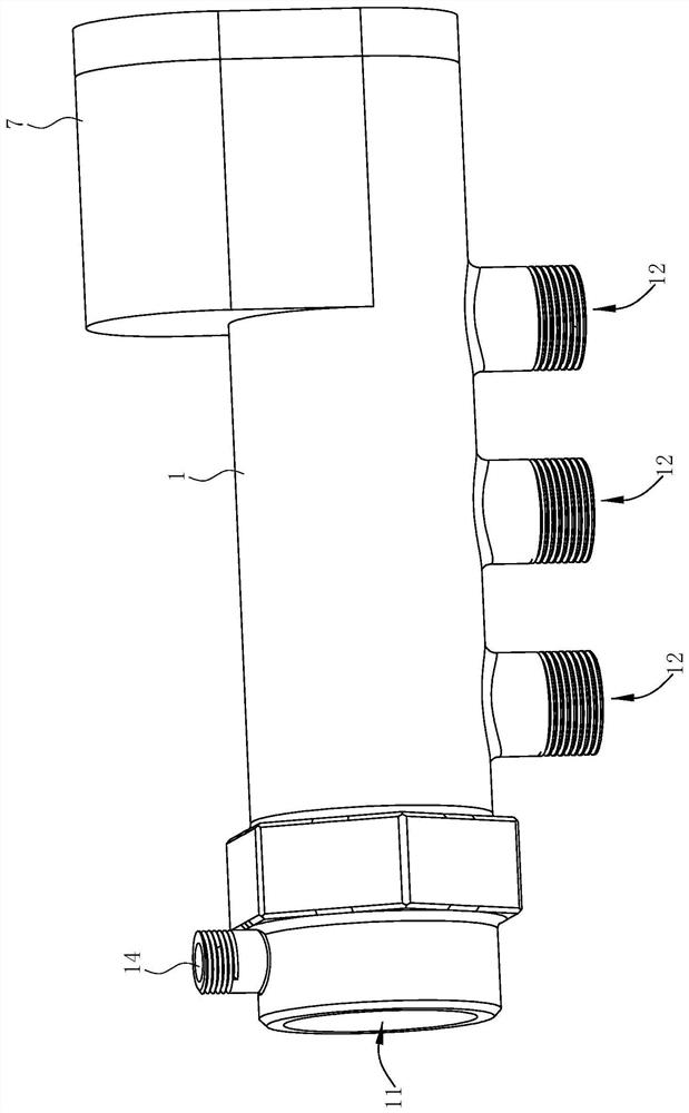
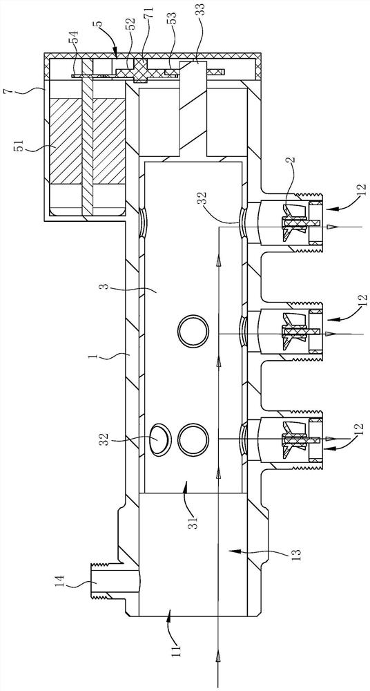
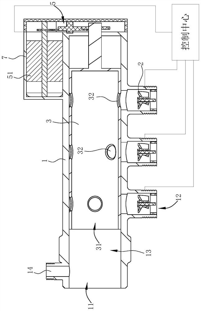
[0035] Such as Figure 1-11As shown, the sub-collector of this preferred embodiment includes a housing 1, a cylinder body 3 and a stepping drive mechanism 5, the housing 1 has a hollow inner cavity 13, and the housing 1 is provided with a first opening 11 and at least two There are two second openings 12 arranged at intervals, the first opening 11 and the second opening 12 are both in communication with the inner cavity 13 . Along the direction of water flow, the second opening 12 is located downstream of the first opening 11. At this time, the sub-catchment is used as a water distribution pipe, that is, the first opening 11 is used as a water inlet, and the second opening 12 is used as a water outlet. In this embodiment, the housing 1 is roughly cylindrical, one end of the housing 1 is opened to form a first opening 11, and the other end is ...


PUM


Abstract

The invention relates to a sub-collector comprising a housing, a cylinder and a driving mechanism. The housing has a hollow inner cavity. The housing is provided with a first opening and at least two second openings arranged at intervals. The cylinder is located in the housing In the inner cavity of the second opening and axially extending along the interval setting direction of the second opening, the outer peripheral surface of the cylinder is always in contact with the wall surface of the housing where the second opening of the housing is located, and the end wall of the cylinder is provided with a The first opening is always connected to the first through hole; the outer peripheral wall of the cylinder is provided with at least two sets of second through holes at intervals along the axial direction; the driving mechanism drives the cylinder to rotate step by step. In the present invention, a second through hole group capable of controlling the on-off and on-off quantity of the second opening of the casing is provided on the cylinder body, so that no control valve is provided at each second opening to control the water flow.

Description

technical field [0001] The invention belongs to the technical field of heating, and in particular relates to a water diversion device. Background technique [0002] In recent years, the use of geothermal heating in home decoration has gradually increased, and the application of sub-collectors matched with geothermal heating systems has become more and more extensive. The sub-collector is composed of a water-distributing main pipe and a water-collecting main pipe. The water-dividing main pipe is connected to the water supply pipe of the pipe network system. Its main function is to distribute the hot water from the pipe network system to the room through the floor heating pipe buried under the floor. Each room that needs to be heated. When hot water flows in the floor heating pipe, heat is transferred to the floor, and then radiated to the room through the floor. The other end of the floor heating pipe is connected to the water collecting main pipe of the sub-catchment, and ...

Claims


Application Information

Patent Timeline
Patent Type & Authority Patents(China)
IPC IPC(8): F24D3/10F24D19/10F16K11/07F16K11/085F16K31/04
CPCF16K11/0716F16K11/085F16K31/043F16K31/047F24D3/1066F24D19/1009F24D2220/02
Inventor 金晶
Owner NINGBO FOTILE KITCHEN WARE CO LTD
Why Eureka
Try Eureka