Roadbed monitoring device

A technology for monitoring devices and subgrades, which is applied to surveying devices, on-site foundation soil surveying, surveying and navigation, etc., can solve the problems of inaccurate monitoring results and inaccurately reflect settlement data, etc., to improve monitoring accuracy and detection accuracy Effect

Pending Publication Date: 2019-10-29
CHINA RAILWAY FIFTH SURVEY & DESIGN INST GRP
View PDF0 Cites 4 Cited by
  • Summary
  • Abstract
  • Description
  • Claims
  • Application Information

AI Technical Summary

Problems solved by technology

[0004] However, in the process of practical application, the inventor found that the monitoring results of the above-mentioned device were not accurate enough to accurately reflect the settlement data

Method used


Image

  • Roadbed monitoring device
  • Roadbed monitoring device
  • Roadbed monitoring device

Examples


Embodiment 1

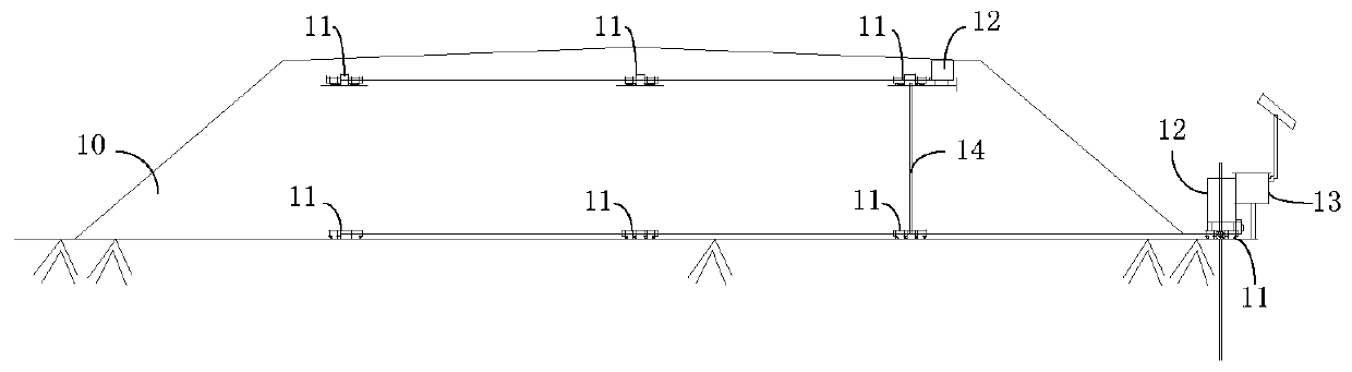
[0040] This embodiment provides a roadbed monitoring device for monitoring the settlement state of the roadbed. Compared with traditional monitoring methods, the monitoring device provided by this embodiment has higher monitoring accuracy.

[0041] According to the different sizes, the roadbed is roughly divided into two categories: the first type of roadbed is divided into: the body layer, the bottom layer and the surface layer from bottom to top, and the bottom of the body layer is called the base layer of the roadbed; the height of the second type of roadbed is higher. Low, from bottom to top is divided into: bottom layer and surface layer, then the bottom of the bottom layer is called the base layer of the subgrade.

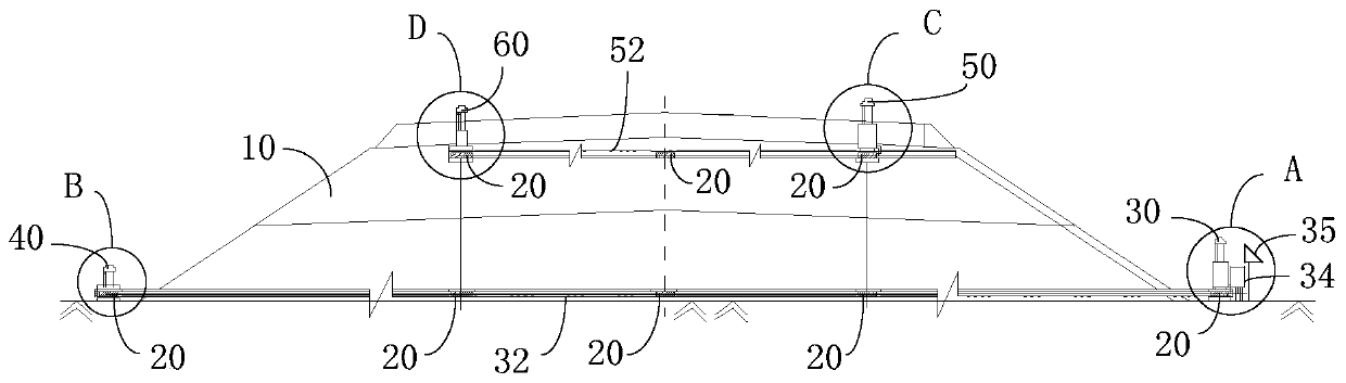
[0042] figure 2 A structural schematic diagram of the roadbed monitoring device provided in the embodiment of the present application applied to monitor the roadbed. In the present embodiment, the vertical direction is referred to as: vertical or vertical,...


PUM


Abstract

The embodiment of the invention provides a roadbed monitoring device, which comprises: a plurality of displacement sensors respectively arranged at each to-be-measured point of a surface layer and a substrate layer of a roadbed, the displacement sensors located on the surface layer of the roadbed are connected to form a surface layer measuring line, and the displacement sensors located on the substrate layer of the roadbed are connected to form a substrate layer measuring line; a substrate layer reference satellite coordinate sensor arranged above the first displacement sensor located on the substrate layer of the roadbed; a substrate layer checking satellite coordinate sensor arranged above the second displacement sensor located on the substrate layer of the roadbed; a surface layer reference satellite coordinate sensor arranged above the third displacement sensor positioned on the surface layer of the roadbed; a surface layer checking satellite coordinate sensor arranged above the fourth displacement sensor located on the surface layer of the roadbed; processing equipment electrically connected with each displacement sensor and each satellite coordinate sensor; a power supply device. According to the roadbed monitoring device provided by the embodiment of the invention, the roadbed settlement monitoring precision can be improved.

Description

technical field [0001] The present application relates to roadbed monitoring technology, in particular to a roadbed monitoring device. Background technique [0002] The roadbed is the foundation of railway facilities, and the stability of the roadbed determines whether the railway operation is safe. During the construction of railway facilities and the operation of the railway, it is necessary to monitor the subgrade. When the subsidence of the subgrade is detected, corresponding measures must be taken to avoid serious impact on the operation of the railway. [0003] At present, the monitoring of the subgrade usually adopts a plurality of differential pressure static levels distributed at various points of the subgrade to be measured, so as to monitor the settlement of the points to be measured. figure 1 It is a structural schematic diagram of the roadbed monitoring device used in the related art to monitor the roadbed. Such as figure 1 As shown, a static level 11 is prov...

Claims


Application Information

Patent Timeline
Patent Type & Authority Applications(China)
IPC IPC(8): G01C5/00G01C15/02G01C25/00E02D1/00
CPCE02D1/00G01C5/00G01C15/02G01C25/00
Inventor 汤友富时洪斌刘柏林毛忠良唐沛丁新红邓文庆张成钢冷长明冯永阳江涛陶玉洋胡传家
Owner CHINA RAILWAY FIFTH SURVEY & DESIGN INST GRP
Why Eureka
Try Eureka