External chest compression device for cardiopulmonary resuscitation

A cardiopulmonary resuscitation and bar pressing technology, applied in cardiac stimulation, therapy, physical therapy, etc., can solve the problems of inability to automatically adjust the compression depth, cumbersome operation of cardiopulmonary resuscitation equipment, affecting the compression efficiency and quality, etc., which is beneficial to rehabilitation and reduces adjustment Mechanical time, ingenious effects of structure

Active Publication Date: 2019-11-01
HEBI CITY PEOPLES HOSPITAL
View PDF10 Cites 3 Cited by
  • Summary
  • Abstract
  • Description
  • Claims
  • Application Information

AI Technical Summary

Problems solved by technology

[0007] In view of the above situation, in order to overcome the defects of the prior art, the present invention provides a cardiopulmonary resuscitation chest compression device, which effectively solves the complicated operation of the prior art cardiopulmonary resuscitation apparatus, the compression depth is difficult to control, the adaptability is limited, and it cannot be adjusted according to different individuals. To automatically adjust the compression depth, affect the compression efficiency and quality, and delay the rescue time

Method used


Image

  • External chest compression device for cardiopulmonary resuscitation
  • External chest compression device for cardiopulmonary resuscitation
  • External chest compression device for cardiopulmonary resuscitation

Examples


Embodiment Construction

[0019] The specific implementation manners of the present invention will be further described in detail below in conjunction with the accompanying drawings.

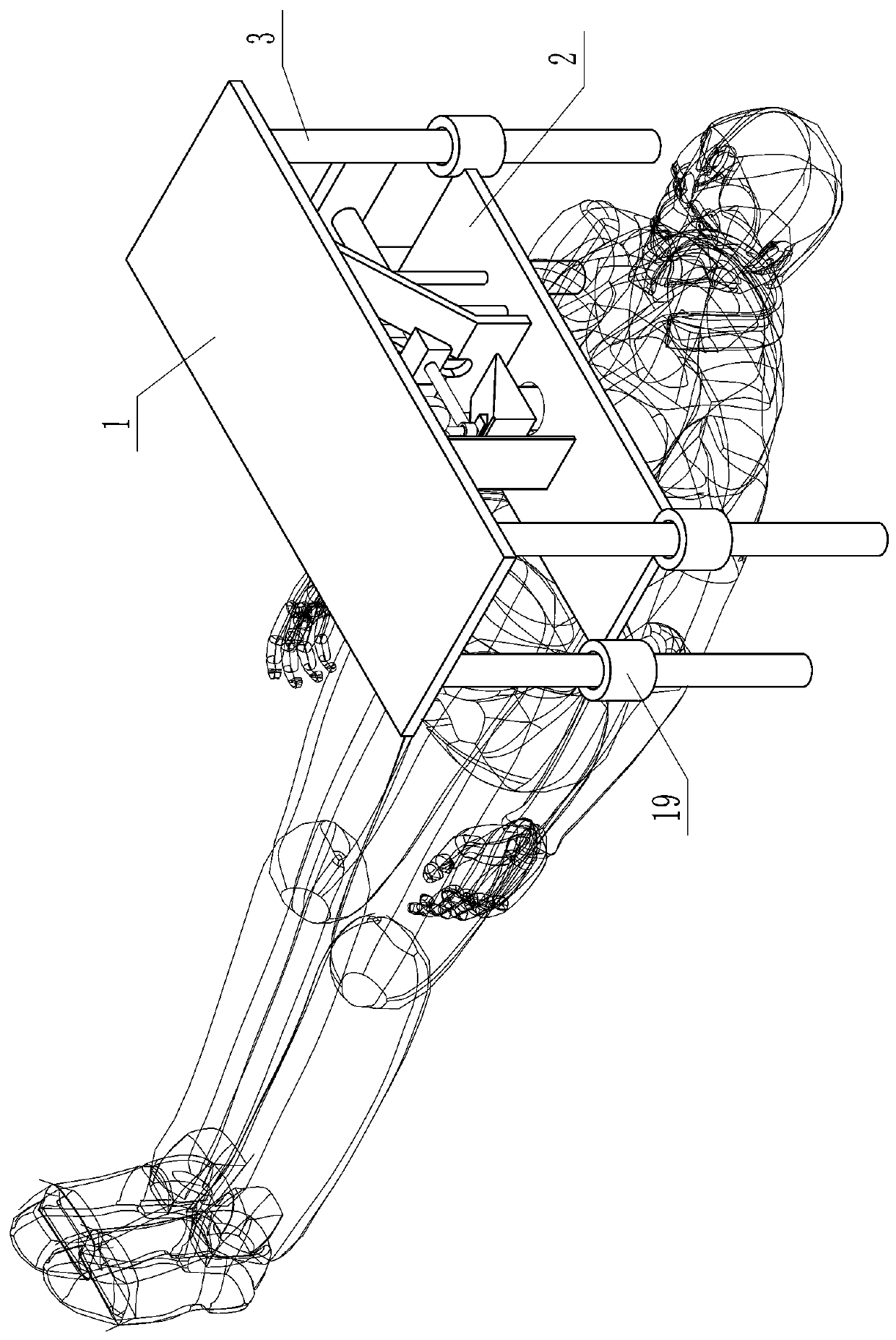
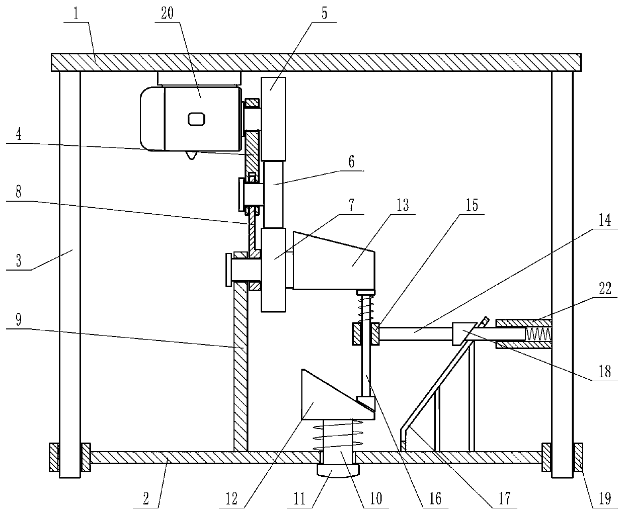
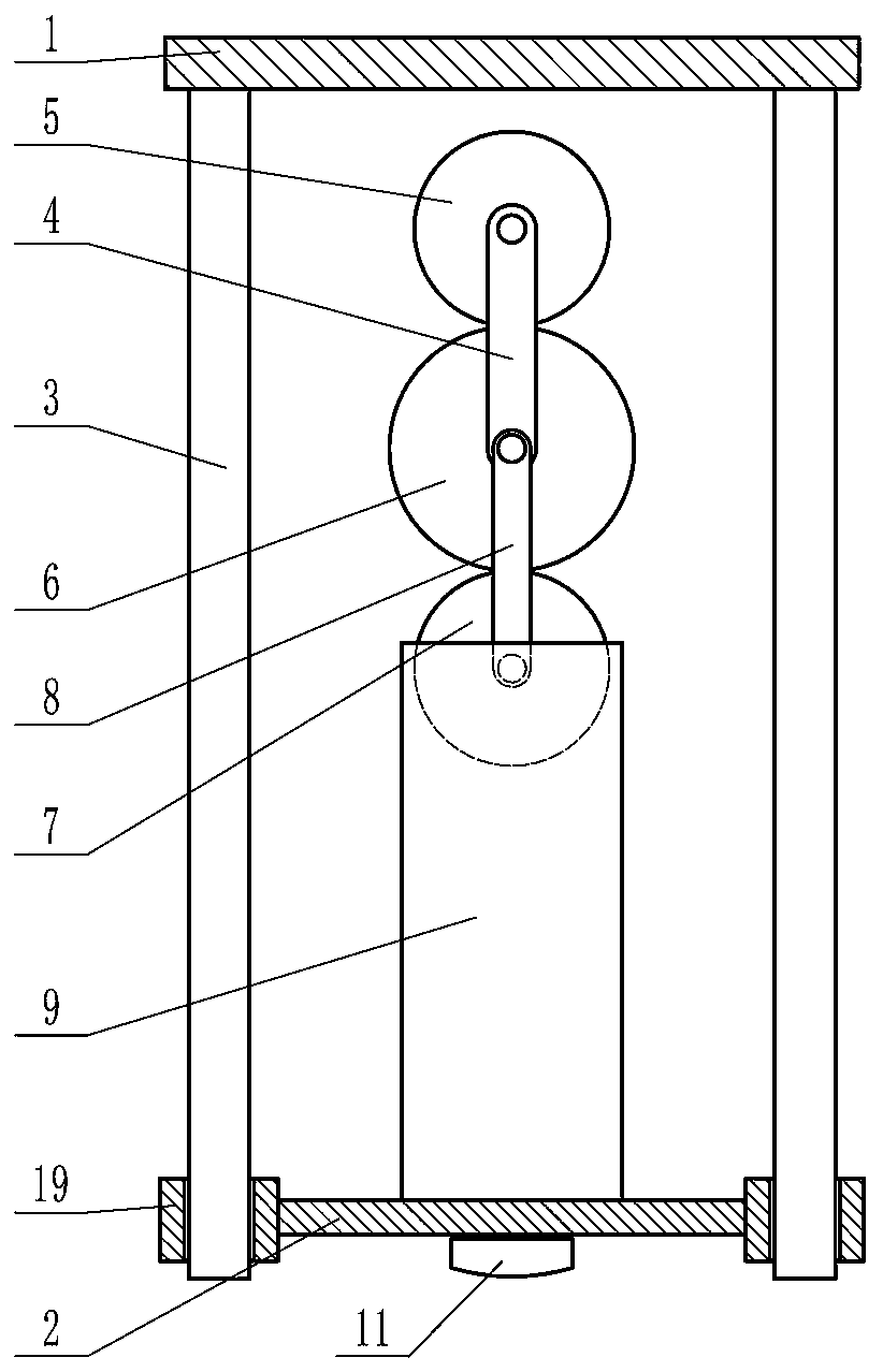
[0020] Depend on Figure 1 to Figure 8 Provided, the present invention includes a horizontal plate 1, the lower side of the plate 1 has a horizontal plate 2 parallel to it and can move up and down, a plurality of vertical support rods 3 are fixed on the lower end of the plate 1, and the horizontal plate 2 can move along the The support rod 3 slides up and down, and the horizontal plate 2 can be fixed on the support rod 3. There is a first connecting rod 4 on the lower side of the flat plate 1, and the first connecting rod 4 is equipped with a first gear 5 that can rotate actively. There are 5 first gears It can rotate but cannot move up and down or left and right. The lower end of the first connecting rod 4 has a transmission gear 6 meshing with the first gear 5. The central axis of the transmission gear 6 is hinged with...


PUM


Abstract

The invention provides an external chest compression device for cardiopulmonary resuscitation, and effectively solves the problems that in the prior art, cardiopulmonary resuscitation apparatuses aretedious to operate, the compression depth is not liable to control, the adaptability is limited, the compression depth cannot be automatically adjusted according to different individuals, the efficiency and quality of compression are influenced, and the rescuing time is delayed. The technical scheme of the external chest compression device for solving the problems is characterized by comprising aslab, wherein a horizontal plate is arranged on the lower side of the slab; supporting rods are fixed to the lower end surface of the slab; a first connecting rod is arranged on the lower side of theslab; a first gear is arranged on the first connecting rod; a transmission gear is arranged at the lower end of the first connecting rod; a second gear is arranged on the lower side of the transmission gear; a second connecting rod is arranged on the left side of the second gear; a vertical plate is arranged on the upper side of the horizontal plate; a pressure rod is arranged on the horizontal plate in a penetrating manner; a pressing block is arranged at the lower end of the pressure rod; a first wedge-shaped block is arranged at the upper end of the pressure rod; a cam is arranged at the right end of the second gear; a horizontal rod is arranged above the right end of the horizontal plate; a vertical rod is arranged at the left end of the horizontal rod; a sloping plate is arranged on the horizontal plate; a sliding groove is formed in the sloping plate; the horizontal rod is arranged in the sliding groove; and a wedge-shaped protrusion is arranged on the horizontal rod.

Description

technical field [0001] The invention relates to the technical field of emergency treatment equipment, in particular to a chest compression device for cardiopulmonary resuscitation. Background technique [0002] Traditional chest resuscitation mostly uses the operator's hands on the chest compression part of the patient to press rhythmically to achieve. In the old guideline, the compression requirements were as follows: the depth of compression depression was 3-5cm, and the compression frequency was 100-120 times / min, so the operation intensity was relatively high. In the actual operation, often because the operator's arm is not straight, resulting in uneven force on the palm; or because the operator's physical exertion is too large, the operator needs to be replaced frequently and many other reasons, which affect the effect of pressing, especially prone to rib fractures and other complications. [0003] In the new guidelines, "For children (including infants [less than one...

Claims


Application Information

Patent Timeline
Patent Type & Authority Applications(China)
IPC IPC(8): A61H31/00
CPCA61H31/006A61H2201/1207A61H2205/084
Inventor 李奕冰席佳佳
Owner HEBI CITY PEOPLES HOSPITAL
Why Eureka
Try Eureka