
Guider polishing clamp

A technology of guides and fixtures, which is applied in the direction of grinding workpiece supports, etc., can solve the problems of easy deformation of the exhaust edge and difficulty in controlling the size of the grinding, and achieve the effect of improving grinding efficiency and ensuring dimensional accuracy

Active Publication Date: 2019-11-01
CHINA HANGFA SOUTH IND CO LTD
View PDF6 Cites 0 Cited by
  • Summary
  • Abstract
  • Description
  • Claims
  • Application Information

AI Technical Summary

Problems solved by technology

[0007] The invention provides a guide grinding fixture to solve the problems that the exhaust edge is easily deformed and the grinding size is difficult to control when manually grinding to remove the subsidy on the exhaust edge of the blade of the guide

Method used


Image

  • Guider polishing clamp
  • Guider polishing clamp
  • Guider polishing clamp

Examples


Embodiment Construction

[0031] It should be noted that, in the case of no conflict, the embodiments in the present application and the features in the embodiments can be combined with each other. The present invention will be described in detail below with reference to the accompanying drawings and examples.

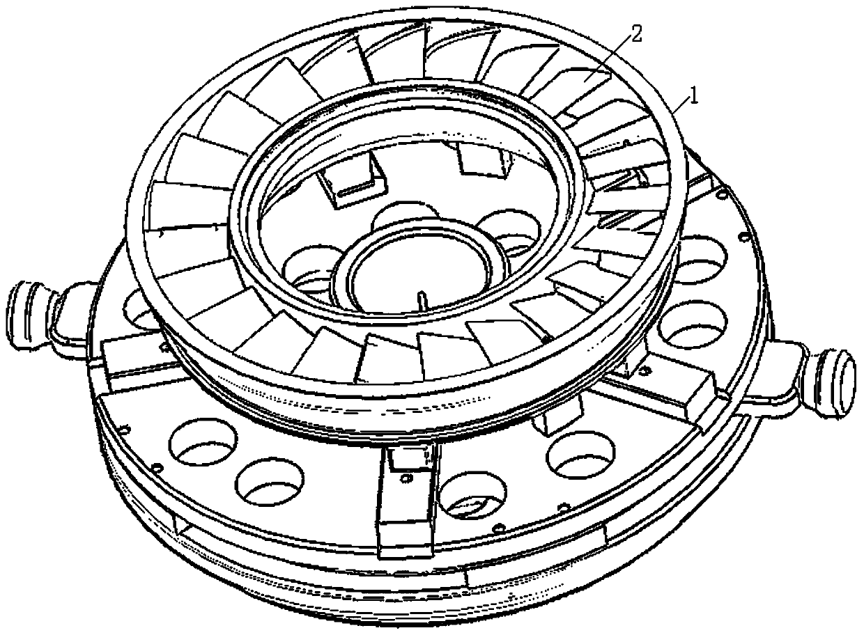
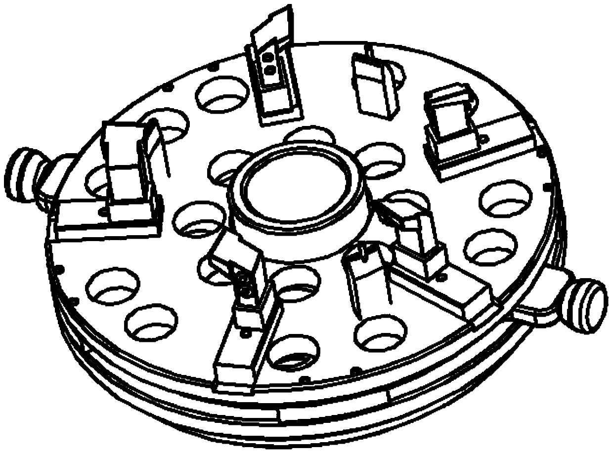
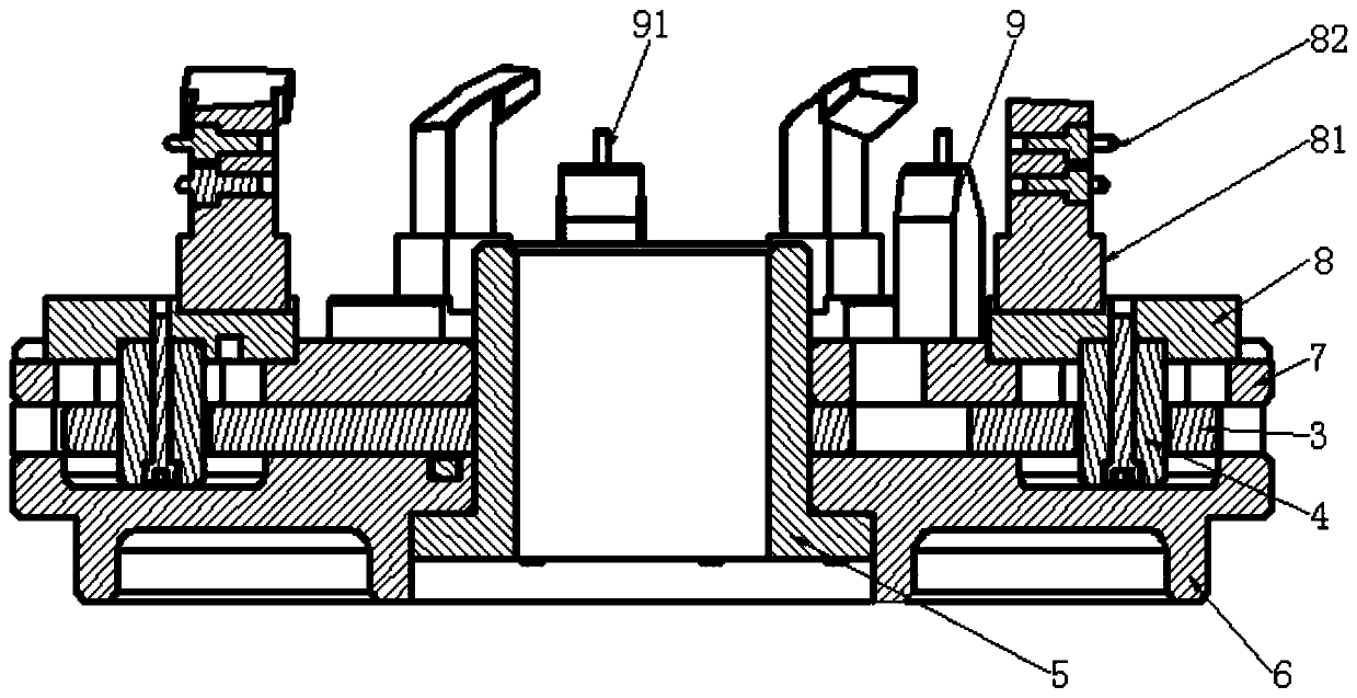
[0032] figure 1 It is a schematic diagram of positioning the guide by the guide grinding jig of the preferred embodiment of the present invention; figure 2 is a three-dimensional schematic diagram of a guide grinding jig in a preferred embodiment of the present invention; image 3 is a cross-sectional view of a guide grinding jig of a preferred embodiment of the present invention; Figure 4 It is a schematic diagram of the drive rod passing through the movable hole in the preferred embodiment of the present invention; Figure 5 It is a schematic diagram of a supporting block and a positioning pin supporting a blade in a preferred embodiment of the present invention; Figure 6 It is a schem...


PUM


Abstract

The invention provides a guider polishing clamp. The guider polishing clamp is used for locating a guider, so that the exhaust edges of blades of the guiderare conveniently polished. The guider polishing clamp comprises a clamp body, an axial locating mechanism which is arranged on the clamp body and used for abutting against the intake edges of the blades of the guider so as to conduct axial locating on the guider, a circumferential locating mechanism which is arranged on the clamp body and used for abutting against blade backs and blade basins of the blades of the guider so as to conduct circumferential locating on the guider, and a central locating mechanism which is arranged on the clamp body and used for aligning the center of the guider with the center of the clamp body so as to conduct central locating on the guider. When the exhaust edges of the blades are manually polished, since axial locating, circumferential locating and central locating are conducted on the guider at the same time, accurate locating of the guider is achieved; and besides, a height datum, an angular datum, a center datum and other reference datum are provided, so that the polishing dimension can be wellcontrolled; and in this way, the dimension precision of the blades is guaranteed, and the polishing efficiency is improved.

Description

technical field [0001] The invention relates to the technical field of guider grinding, in particular to a guider grinding jig. Background technique [0002] When casting the guide, due to the limitation of materials, process structure, and manufacturability, etc., under-casting defects often occur. In order to improve the filling of the casting, subsidies are often added on the exhaust side to meet the integrity of the casting. [0003] After the casting is formed, the subsidy needs to be removed by manual grinding, but in the actual production process, it still cannot meet the requirements of the design drawings. The main reasons are as follows: [0004] 1. The material used for the casting is relatively soft, and the exhaust edge of the casting is easily deformed. [0005] 2. When grinding by hand, it is difficult to control the grinding size because the operator completely depends on the visual control of the grinding. [0006] 3. When manually grinding, the exhaust ed...

Claims


Application Information

Patent Timeline
IPC IPC(8): B24B41/06
CPCB24B41/067
Inventor 闵相国杨超杨星星罗贵敏侯正乾
Owner CHINA HANGFA SOUTH IND CO LTD
Learn More