Special through-hole drilling fixture for cylindrical part

A technology for drilling through holes and cylindrical shapes, which is applied in the field of drilling tooling for cylindrical parts, can solve the problems of difficult positioning of the drill bit, poor position accuracy, and the drill bit is easy to break, and achieves easy positioning, not easy to break, guaranteed size and The effect of positional accuracy

Active Publication Date: 2012-02-01
HARBIN JIANCHENG GRP
View PDF4 Cites 24 Cited by
  • Summary
  • Abstract
  • Description
  • Claims
  • Application Information

AI Technical Summary

Problems solved by technology

[0003] In order to solve the problem that when a cylindrical part is drilled through a hole on the outer wall, due to no processing plane, the positioning of the drill bit is difficult and the vibration is large, resulting in poor hole size and position accuracy and the problem that the drill bit is easy to break, a cylinder is provided. It is a special tool for drilling through-holes of shaped parts, and the through-holes completed in one process are divided into two processes by using the first positioning pin.

Method used


Image

  • Special through-hole drilling fixture for cylindrical part
  • Special through-hole drilling fixture for cylindrical part
  • Special through-hole drilling fixture for cylindrical part

Examples


specific Embodiment approach 1

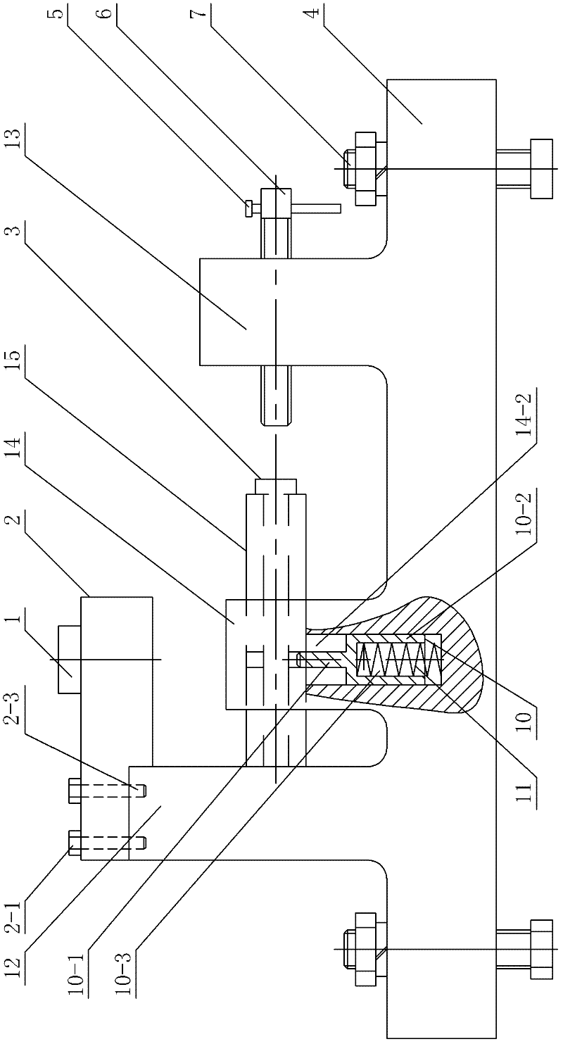
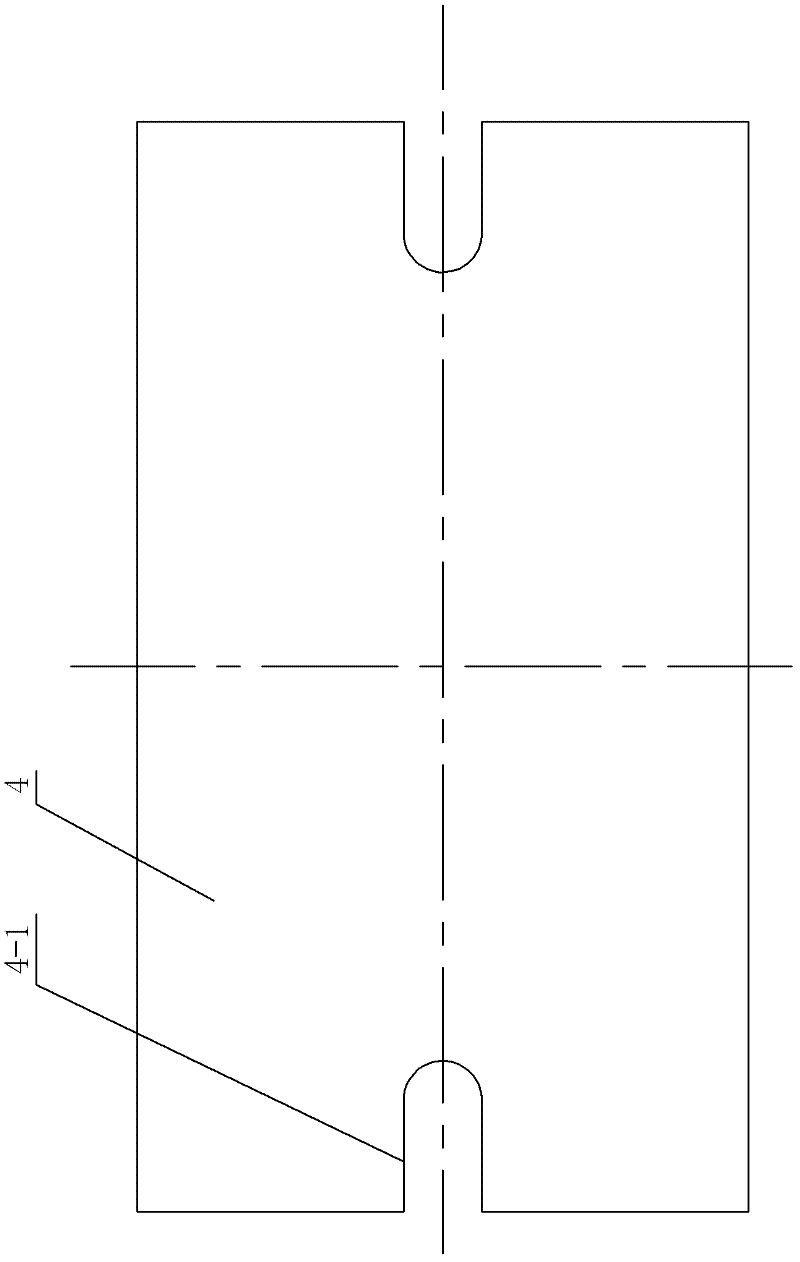
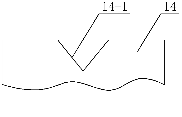
[0007] Specific implementation mode one: combine Figure 1-Figure 6 Describe this embodiment, a special tooling for drilling through holes in cylindrical parts in this embodiment, the special tooling includes a drill sleeve 1, a pressure plate assembly 2, a positioning block 3, a base 4, a screw rod 6, a positioning bolt assembly 7, The first positioning pin 10, spring 11, high vertical plate 12, short vertical plate 13 and support vertical plate 14; The pressing plate assembly 2 comprises pressing plate 2-2 and two second positioning pins 2-3; Processed on the pressing plate 2-2 A drill sleeve hole 2-4, the drill sleeve hole 2-4 is located on the center line of the pressure plate 2-2 in the length direction, one end of the drill sleeve 1 is inserted into the drill sleeve hole 2-4, and the base 4 is located on the two end faces of the length direction There is an open positioning bolt groove 4-1 (for fixing the tooling on the working platform of the drilling machine) in the mi...

specific Embodiment approach 2

[0009] Specific implementation mode two: combination figure 1 , Figure 4 and Figure 5 Explain, one end of the lower end surface of the pressing plate 2-2 of the present embodiment is processed with a gap 2-6 along the width direction of the pressing plate 2-2, the upper end surface of the gap 2-6 is a plane, and the upper end of the high vertical plate 12 is placed on the pressing plate 2-2 inside the gap 2-6. The support vertical plate 14 and the base 4 can be fixed firmly. Other components and connections are the same as those in the first embodiment.

specific Embodiment approach 3

[0010] Specific implementation mode three: combination figure 1 , Figure 4 and Figure 5 Note that the pressing plate assembly 2 of this embodiment further includes four connecting bolts 2-1; the pressing plate 2-2 and the base 4 are fixedly connected by the four connecting bolts 2-1. Other compositions and connections are the same as those in Embodiment 1 or 2.


PUM


Abstract

The invention provides a special through-hole drilling fixture for a cylindrical part, and relates to a drilling fixture for a cylindrical part, which is used for solving the problems such as poor size and position precision of the hole and easy rupture of a drill bit caused by no machining plane, difficult drill bit localization and greater vibration when the through hole is drilled on the outer side wall of the cylindrical part. In the invention, a high vertical plate, a low vertical plate and a support vertical plate are fixedly connected on a base, wherein, the support vertical plate is positioned between the high vertical plate and the low vertical plate; a V-shaped groove is machined at the middle part of the upper end surface of the support vertical plate; a screw is in threaded connection with a threaded through hole of the low vertical plate; a first blind hole is machined on the bottom of the V-shaped groove; a pressure plate and the high vertical plate are located by two second locating pins; a locating block is composed of a large-diameter cylinder and a small-diameter cylinder which are integrated together, and the small-diameter cylinder is matched with an inner hole of the part; and a first locating pin is composed of a large-diameter pin and a small-diameter pin which are integrated into a whole, the first locating pin is arranged in the first blind hole of the support vertical plate, and a spring is arranged in a second blind hole of the first locating pin. The special through-hole drilling fixture provided by the invention is used for localization when the through hole is drilled on the cylindrical part.

Description

technical field [0001] The invention relates to a drilling tool for cylindrical parts. Background technique [0002] Because there is no special tooling when drilling a through hole on the outer wall of a cylindrical part, the drill bit is directly drilled on the arc surface during processing, there is no processing plane, and the positioning of the drill bit is difficult. are also arcuate surfaces (see Figure 7 ), the vibration of the drill bit is large during processing, resulting in poor size and position accuracy of the through hole, which cannot meet the process requirements, and the drill bit is easily broken. Contents of the invention [0003] The invention aims to solve the problem that when drilling a through hole on the outer wall of a cylindrical part, because there is no processing plane, the positioning of the drill bit is difficult and the vibration is large, resulting in poor hole size and position accuracy and the problem that the drill bit is easy to brea...

Claims


Application Information

Patent Timeline
Patent Type & Authority Applications(China)
IPC IPC(8): B23B41/00B23B49/02B23Q3/02B23Q3/06
Inventor 高立栋于晶李利华
Owner HARBIN JIANCHENG GRP
Why Eureka
Try Eureka