

A printing inking device
An ink tank and ink transfer roller technology, which is applied in printing, printing presses, general parts of printing machinery, etc., can solve the problems of uneven quality of printed products, uneven ink of the ink transfer roller, and reduced ink activity. Smooth ink process, increase practicability, prevent viscous precipitation
Active Publication Date: 2022-05-31
东莞同森印刷有限公司
View PDF10 Cites 0 Cited by
- Summary
- Abstract
- Description
- Claims
- Application Information
AI Technical Summary
Problems solved by technology
[0003] Modern printing machines are generally composed of plate loading, inking, embossing, paper feeding and other mechanisms. With the gradual improvement of people's requirements for printing quality, the uniformity of smearing has always been one of the technical difficulties. The existing inking device's inking The contact range between the method and the ink transfer roller is fixed, so that the ink around the ink transfer roller is uneven during the ink transfer process, resulting in uneven quality of printed products. At the same time, the quality of printing ink is one of the main reasons affecting the printing quality. At present The inking device of all kinds of inks will keep the ink still. After a long time, the activity of the ink will decrease and it may solidify. For this reason, we propose a printing inking device
Method used
View moreImage
Smart ImageViewing Examples

Examples
Embodiment Construction
[0025] Below in conjunction with the accompanying drawings in the embodiments of the present invention, the technical solutions in the embodiments of the present invention will be clearly and completely
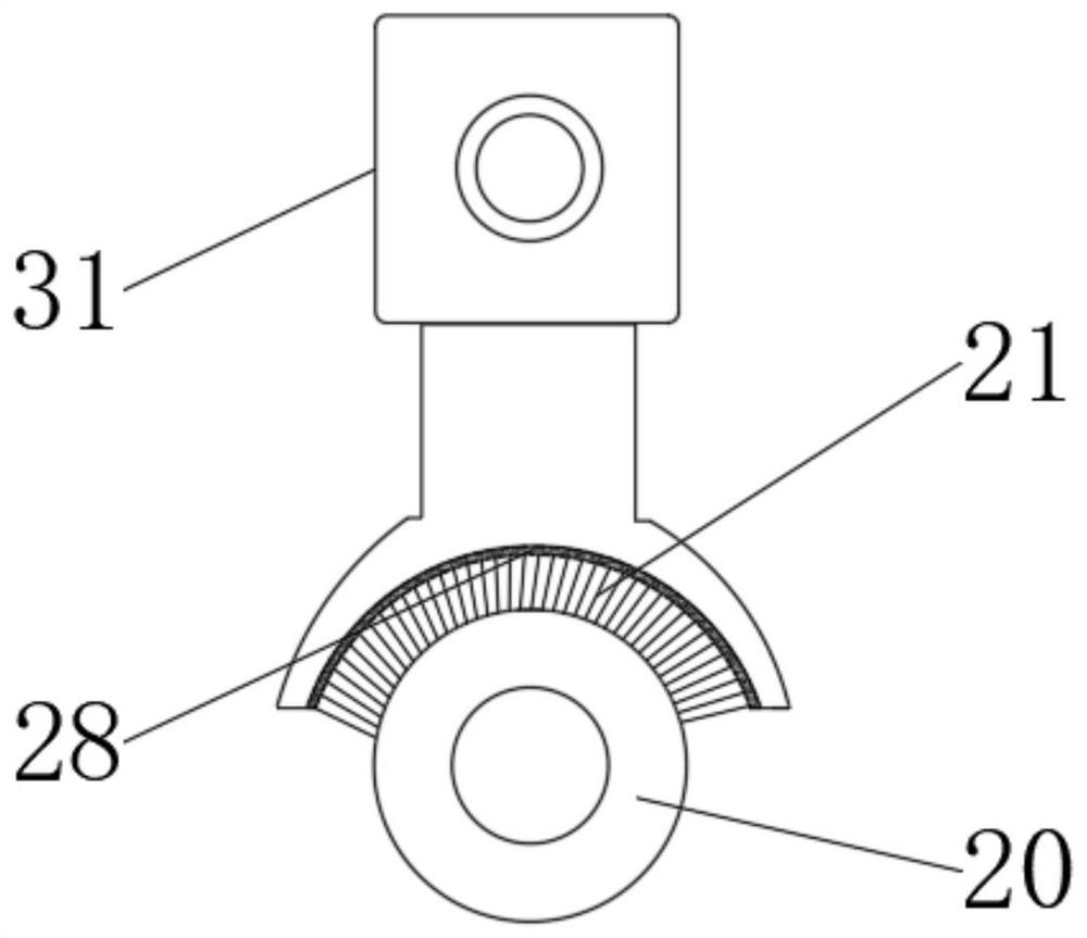
[0033] The bottom of the temporary storage ink cartridge 31 is provided with a layer of ink-absorbing flannel 28 to prevent ink leakage.
Login to View More PUM
 Abstract
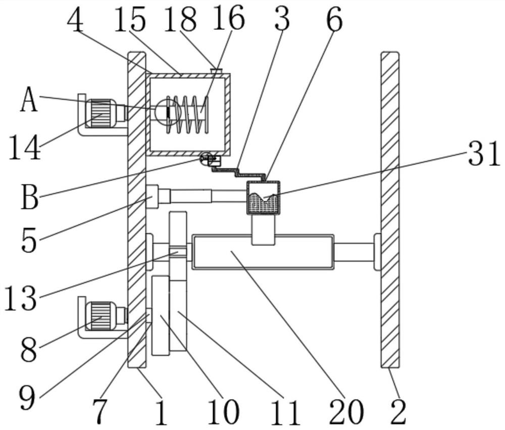
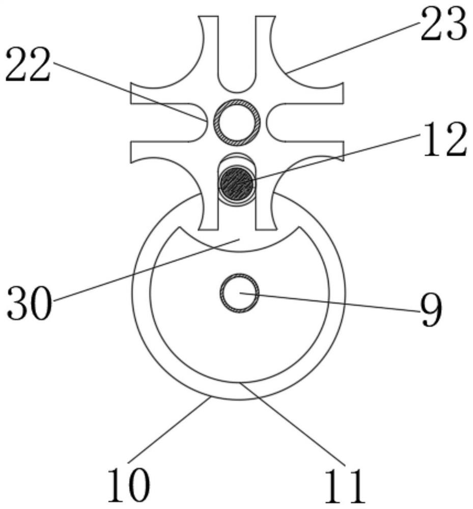
The invention discloses an inking device for printing. An ink storage device is fixedly installed on the top of the first support plate. An electric push rod is fixedly installed on the inner side of the first support plate. Ink device, one end of the telescopic hose communicates with the bottom of the ink storage device, and the other end communicates with the top of the ink transfer device, the bottom of the first support plate is fixedly installed with a drive assembly, and the driving motor of the present invention drives the connecting shaft to make the two A roulette drives the polygonal concave plate to rotate intermittently, and the polygonal concave plate drives the ink transfer roller to rotate intermittently. At the same time, the electric push rod drives the soft brush to perform circular reciprocating motion on the surface of the ink transfer roller, so that the ink passes through the soft brush evenly and comprehensively. Brushing to the surface of the ink transfer roller, the invention solves the problem of uniformity of ink smearing, the ink is applied evenly, the inking process is stable, and the work efficiency is improved.
Description
A printing inking device technical field [0001] The present invention relates to the technical field of printing press accessories, in particular to a printing inking device. Background technique Printing is the process of making texts, pictures, photos, anti-counterfeiting and other manuscripts through plate making, inking and pressure, so that the ink is transferred to the The technique of mass reproduction of the contents of an original on the surface of materials such as paper, fabric, plastic and leather. Modern printing press is generally composed of plate-loading, ink-coating, embossing, paper-feeding and other mechanisms. With the gradual improvement of smearing, the uniformity of application has always been one of the technical difficulties. The inking method of the existing inking device is connected with the ink transfer roller. The contact range is fixed, which makes the ink around the ink transfer roller uneven during the ink transfer process, resulting ...
Claims
Login to View More Application Information
Patent Timeline
 Patent Type & AuthorityPatents(China)
IPC IPC(8): B41F31/02B41F31/03B41F31/10B41F31/00B01D29/01
CPCB41F31/02B41F31/03B41F31/10B41F31/002B01D29/01
Inventor吴松明
Owner东莞同森印刷有限公司