
Temperature-measuring type fault indicator capable of realizing stable clamping on line

A fault indicator, stable technology, applied in the field of temperature measurement type fault indicator, can solve problems such as unfavorable, short-circuit sensor and grounding sensor sliding, unfavorable short-circuit sensor and grounding sensor fixed installation, etc., to achieve convenient adjustment, facilitate operation, and avoid The effect of sliding off

Inactive Publication Date: 2019-11-01
浙江帕博电力科技有限公司
View PDF12 Cites 1 Cited by
  • Summary
  • Abstract
  • Description
  • Claims
  • Application Information

AI Technical Summary

Problems solved by technology

[0004] The purpose of the present invention is to provide a temperature-measuring type fault indicator that can achieve stable clamping of the line, to solve the temperature-measuring type fault indicator currently on the market proposed by the above-mentioned background technology, in the process of installation and use, When the short-circuit sensor and the grounding sensor are fixed and clamped on the line, it is easy to cause the short-circuit sensor and the grounding sensor to slide on the line, which is not conducive to the fixed installation of the short-circuit sensor and the grounding sensor, and it is inconvenient to adjust the installation angle of the main body of the fault indicator, which is not conducive to Problems with workers operating on fault indicator body

Method used


Image

  • Temperature-measuring type fault indicator capable of realizing stable clamping on line
  • Temperature-measuring type fault indicator capable of realizing stable clamping on line
  • Temperature-measuring type fault indicator capable of realizing stable clamping on line

Examples


Embodiment Construction

[0032] Based on the embodiments of the present invention, all other embodiments obtained by persons of ordinary skill in the art without making creative efforts belong to the protection scope of the present invention.

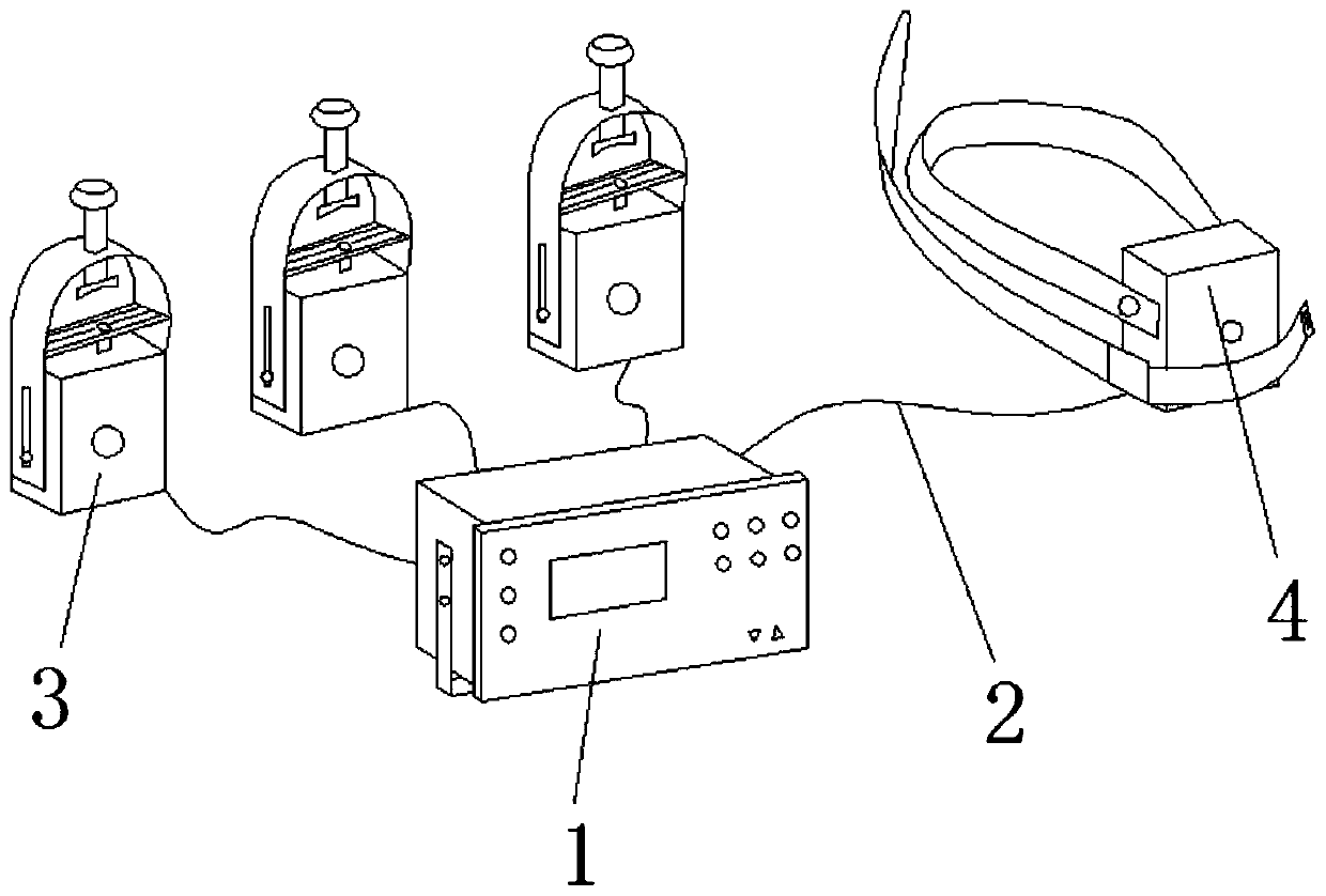
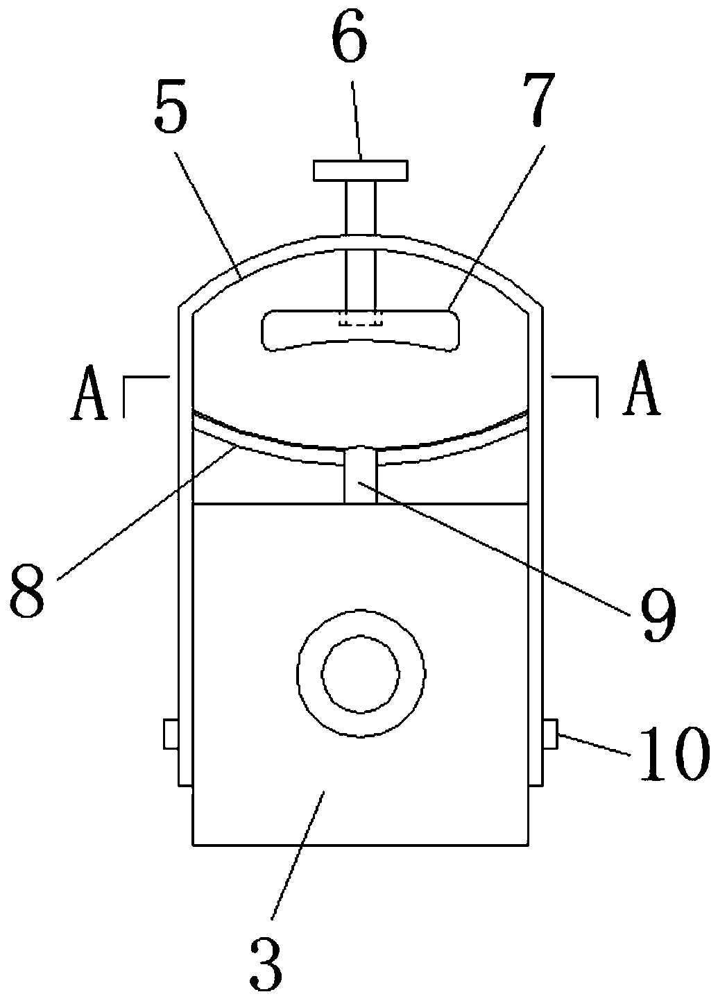
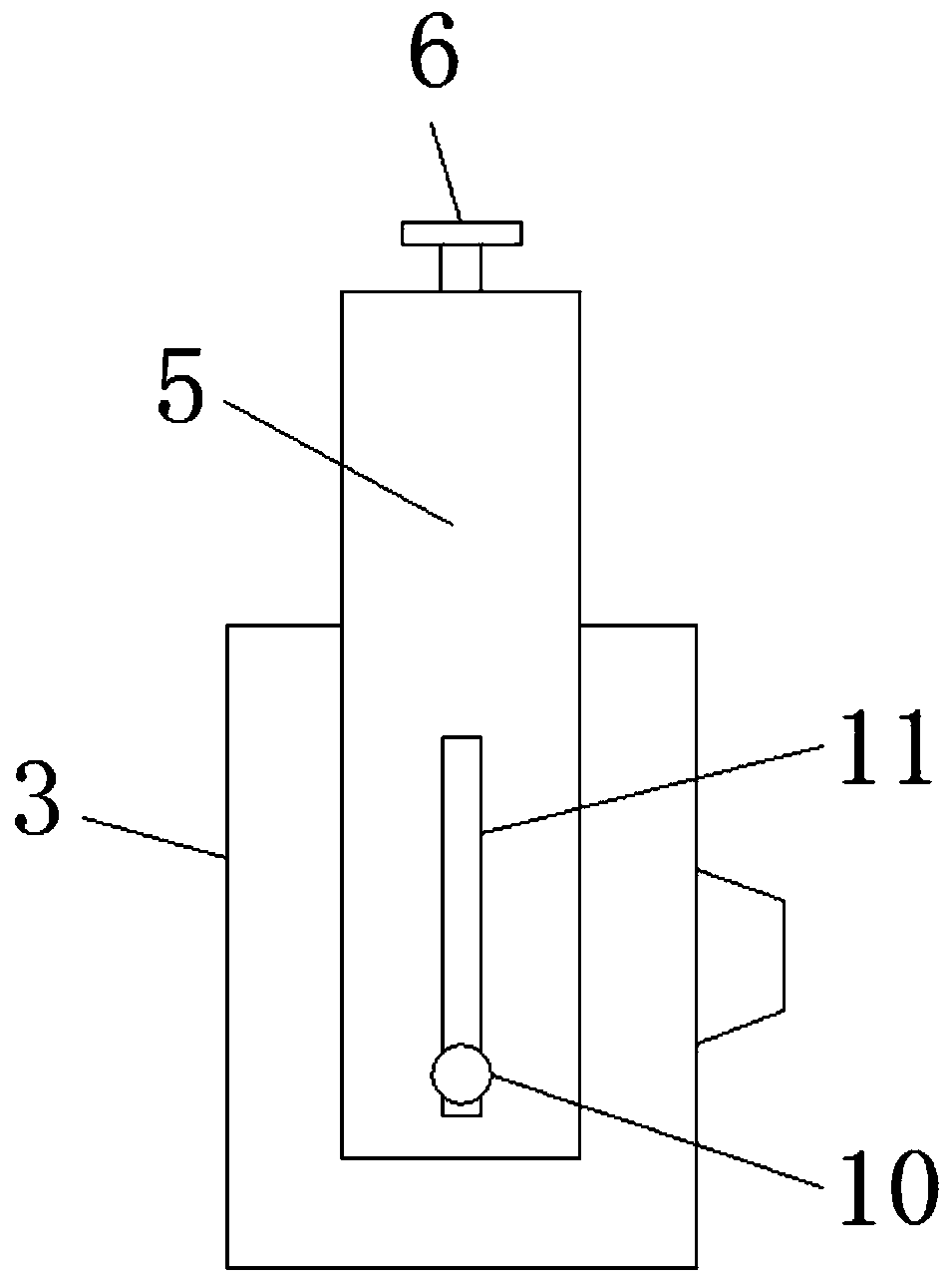
[0033] see Figure 1-13 , the present invention provides a technical solution: a temperature-measuring fault indicator that can realize stable clamping of the line, including a fault indicator main body 1, a transmission optical fiber 2, a short-circuit sensor 3, a grounding sensor 4, an adjustment frame 5, Tightening rod 6, first pressing piece 7, second pressing piece 8, temperature measuring head 9, tightening nut 10, adjustment groove 11, first anti-slip strip 12, temperature measuring hole 13, pressure line hole 14, second anti-slip Strip 15, lifting ring 16, first pressing block 17, screw 18, bandage 19, second pressing block 20, sliding opening 21, mounting frame 22, mounting hole 23, upper pressure plate 24, rotating shaft 25, limit Groove 26 and lower...


PUM


Abstract

The invention discloses a temperature-measuring type fault indicator capable of realizing stable clamping on a line. The indicator comprises a fault indicator main body, a transmission optical fiber,short-circuit sensors, a grounding sensor, a temperature-measuring head, screwing nuts and a bandage; the fault indicator main body is connected with the short-circuit sensor and the ground sensor through the transmission optical fiber, and a regulating rack is arranged on the upper end of each short-circuit sensor; two sides of the fault indicator main body are connected with a mounting rack through a rotating shaft, and screwing nuts are arranged at the upper part of the mounting rack; a lower tension disc is welded on the back of the fault indicator main body, and the upper part of the lower tension disk is connected with an upper tension disc through bolts; and tension holes are formed on the upper tension disc and the lower tension disc. The temperature-measuring type fault indicatorcapable of stably clamping the line can realize the fixation of the short-circuit sensors and the grounding sensor on the detection line, and a worker can conveniently regulated a mounting angle of the fault indicator main body.

Description

technical field [0001] The invention relates to the technical field of fault indicators, in particular to a temperature-measuring type fault indicator capable of stably clamping lines. Background technique [0002] The temperature-measuring fault indicator is an electrical monitoring device for monitoring the line. It is mainly composed of three parts: the main body of the fault indicator, the short-circuit sensor and the grounding sensor. Through the detection of each phase line and the grounding line, the line can be judged. Whether the operation is normal can be timely fed back to the staff to avoid accidents. [0003] However, in the existing temperature-measuring fault indicator, in the process of installation and use, when the short-circuit sensor and the grounding sensor are fixed and clamped on the line, it is easy to cause the short-circuit sensor and the grounding sensor to slide on the line, which is not conducive to the short-circuit sensor and the grounding sens...

Claims


Application Information

Patent Timeline
IPC IPC(8): G01R1/04G01R31/02
CPCG01R1/0425
Inventor 张炬傅宇航
Owner 浙江帕博电力科技有限公司
Learn More