Automatic production line for a gearbox shell plate punching

A technology for automatic production lines and gearbox casings, which is applied in the directions of feeding devices, positioning devices, storage devices, etc., can solve the problems of scratching and abrasion of gearbox shell plates, poor stability of gearbox shell plates, and slow stamping processing efficiency. Anti-scratch damage, easy disassembly, accurate working spacing

Active Publication Date: 2019-11-05
LIUAN LONGXING AUTO PARTS
View PDF6 Cites 1 Cited by
  • Summary
  • Abstract
  • Description
  • Claims
  • Application Information

AI Technical Summary

Problems solved by technology

[0004] The purpose of the present invention is to solve the problem that the stamping efficiency of the top, side and bottom of the gearbox casing is very slow when the existing production line for punching the casing of the gearbox is in use; and the stamping of the casing of the gearbox The precision is very low; the area and angle covered by the stamping production line for the gearbox shell plate are small, so that the stamping production line can only stamp the gearbox shell plate of the same shape and height, and the stamping production line has a small range of work adaptation ;The stamping production line can only stamp a single gearbox shell plate at the same time, which not only has a small utilization rate of space, but also greatly affects the stamping efficiency of the gearbox shell plate; The stability is poor when clamping and moving; and it is easy to scratch and wear with the gearbox shell plate, so an automatic production line for stamping the gearbox shell plate is proposed

Method used


Image

  • Automatic production line for a gearbox shell plate punching
  • Automatic production line for a gearbox shell plate punching
  • Automatic production line for a gearbox shell plate punching

Examples


Embodiment Construction

[0046] The technical solutions of the present invention will be clearly and completely described below in conjunction with the embodiments. Apparently, the described embodiments are only some of the embodiments of the present invention, not all of them. Based on the embodiments of the present invention, all other embodiments obtained by persons of ordinary skill in the art without creative efforts fall within the protection scope of the present invention.

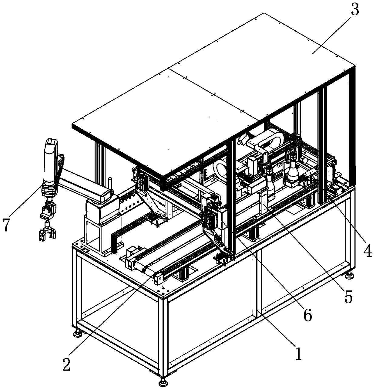
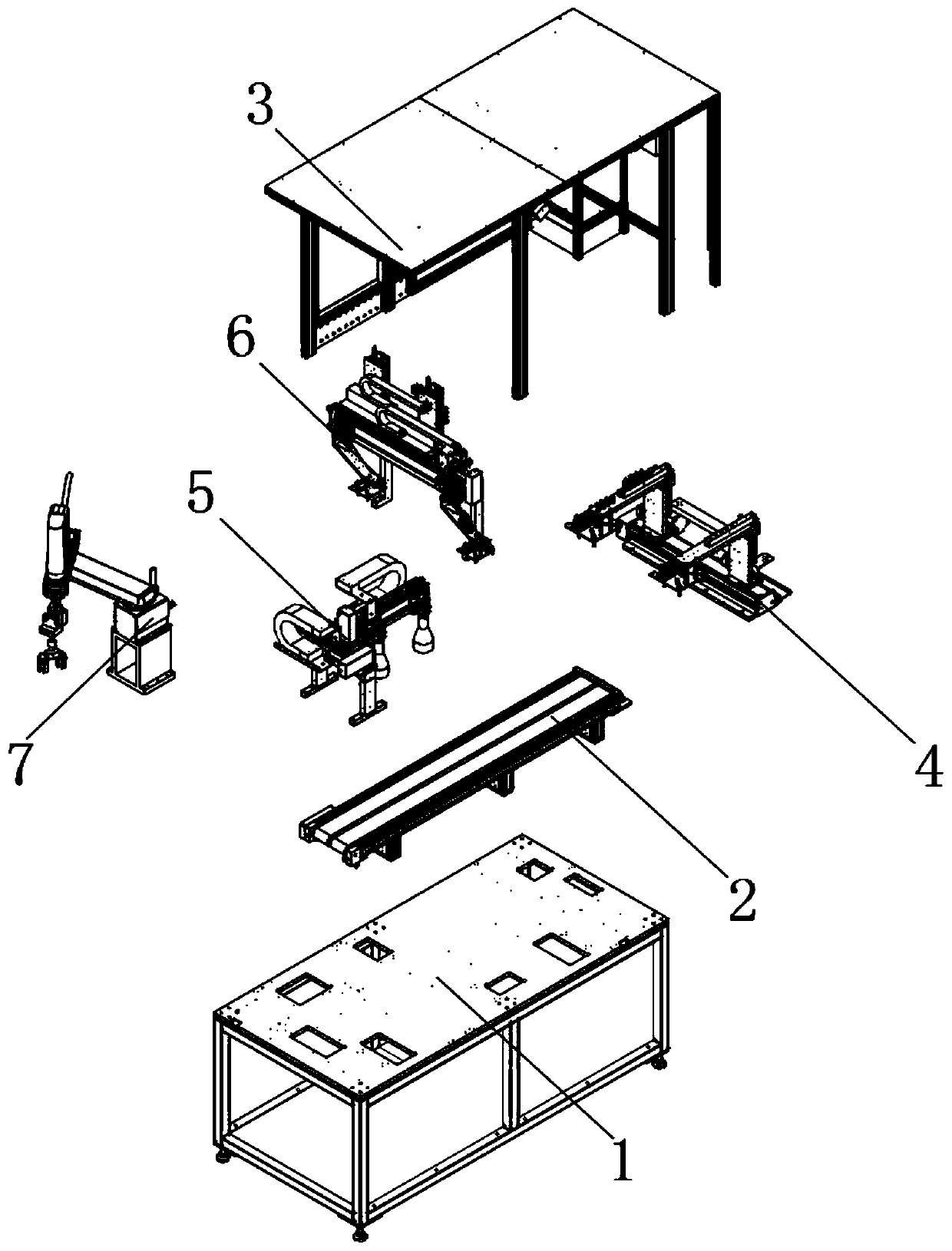
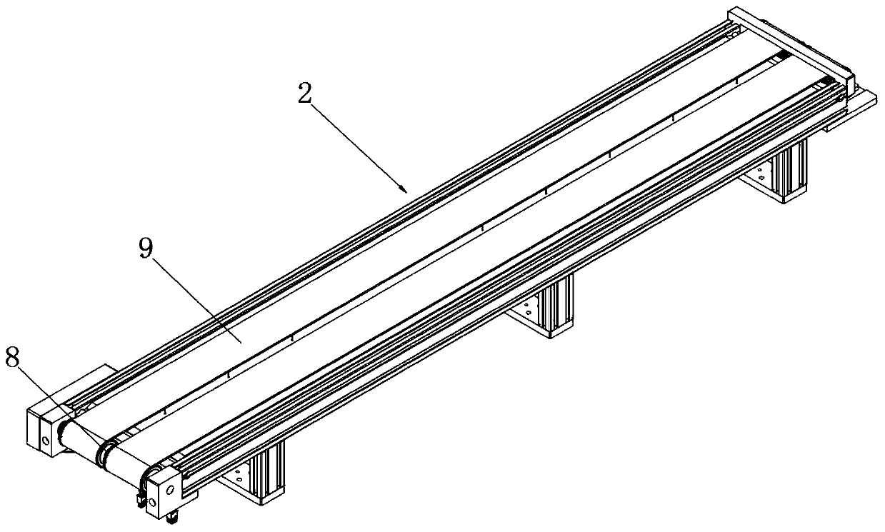
[0047] see Figure 1-13 As shown, an automatic production line for gearbox shell stamping, including a mounting table 1, a transport seat 2, a first punching table 4, a swing table 5, a second punching table 6 and a turning clamp seat 7, the upper end surface of the mounting table 1 A transport seat 2 is provided, and one end of the upper end surface of the installation platform 1 is provided with a first punching table 4, one side of the first punching table 4 is provided with a swing table 5, and one side of the swing tab...


PUM


Abstract

The invention discloses an automatic production line for a gearbox shell plate punching. The automatic production line for a gearbox shell plate punching comprises a mounting table, a conveying seat,a first punching table, a swing adjustment table, a second punching table and an overturning clamping seat; the upper end surface of the mounting table is provided with the conveying seat; and the first punching table is arranged at one end of the upper end surface of the mounting table. A transmission belt on the conveying seat drives a gearbox shell to move and perform conveying; the punching seat on the first punching table performs punching processing on the upper end surface of the gearbox shell plate through a punching block while the gearbox shell plate is moved; and punching processingis simultaneously performed on the two sides of the upper end surface of the gear shell with a plurality of punching seats below two overturning plates, and by matching with two second motors to sleeve a first sliding rail to drive the punching seat to perform punching processing on the gearbox shell in a back and forth movement manner, so that on one hand, the efficiency of performing structurepunching and shaping on the upper end surface of the gearbox shell by the production line is greatly improved, and on the other hand, the working precision of performing punching processing on the upper end surface of the gearbox shell by the production line is higher.

Description

technical field [0001] The invention relates to a production line, in particular to an automatic production line for punching gearbox shell plates, and belongs to the technical field of automatic production line stamping for gearbox shell plates. Background technique [0002] When the gearbox is in use, the shell plate is indispensable. The main function of the shell plate is to protect the internal components of the gearbox and improve the service life of the gearbox. When the gearbox shell is processed, the stamping production line is required to stamp and shape the gearbox shell to ensure a higher fit between the gearbox shell and the gearbox assembly and a stronger connection. [0003] When the existing transmission shell stamping production line is in use, the stamping efficiency of the top, side, and bottom of the gearbox shell is very slow, and the stamping precision of the gearbox shell is very low. The area and angle covered by the stamping of the box shell plate a...

Claims


Application Information

Patent Timeline
Patent Type & Authority Applications(China)
IPC IPC(8): B21D22/02B21D43/10B21D43/12B21D43/18B21D43/14B21D53/90
CPCB21D22/02B21D43/105B21D43/12B21D43/145B21D43/18B21D53/90
Inventor 张传如
Owner LIUAN LONGXING AUTO PARTS
Why Eureka
Try Eureka