
Laser light path system and double-head laser marking machine

An optical path system and laser technology, applied in laser welding equipment, welding equipment, metal processing equipment, etc., can solve the problems of easily damaged mirror group, complex optical path structure of optical splitting module, low output power of marking machine, etc., and achieve simple and compact structure , strong optical path stability, and high beam quality

Active Publication Date: 2019-11-05
HANS LASER TECH IND GRP CO LTD
View PDF10 Cites 4 Cited by
  • Summary
  • Abstract
  • Description
  • Claims
  • Application Information

AI Technical Summary

Benefits of technology

This patented technology describes an improved way for generating coherence between different colors (called color lights). It uses multiple components that work together like one another but separate from each other's design. These designs make it easier to manufacture them while also improving their overall performance over time due to stronger connections made during use.

Problems solved by technology

This patented technical problem addressed by this patents relates to improving the accuracy and reliance on laser printing for various applications such as industrial manufacturing processes where precise patterns are needed due to their importance in industry today's competitive marketplace.

Method used


Image

  • Laser light path system and double-head laser marking machine
  • Laser light path system and double-head laser marking machine
  • Laser light path system and double-head laser marking machine

Examples


Embodiment Construction

[0038] In order to facilitate the understanding of the present invention, the invention will be described more fully below with reference to the associated drawings. Preferred embodiments of the invention are shown in the accompanying drawings. However, the present invention can be embodied in many different forms and is not limited to the embodiments described herein. On the contrary, these embodiments are provided to make the understanding of the disclosure of the present invention more thorough and comprehensive.

[0039] Unless otherwise defined, all technical and scientific terms used herein have the same meaning as commonly understood by one of ordinary skill in the technical field of the invention. The terms used herein in the description of the present invention are for the purpose of describing specific embodiments only, and are not intended to limit the present invention.

[0040] It should be noted that the words "upper", "lower", "upper end", "lower end", "bottom...


PUM


Abstract

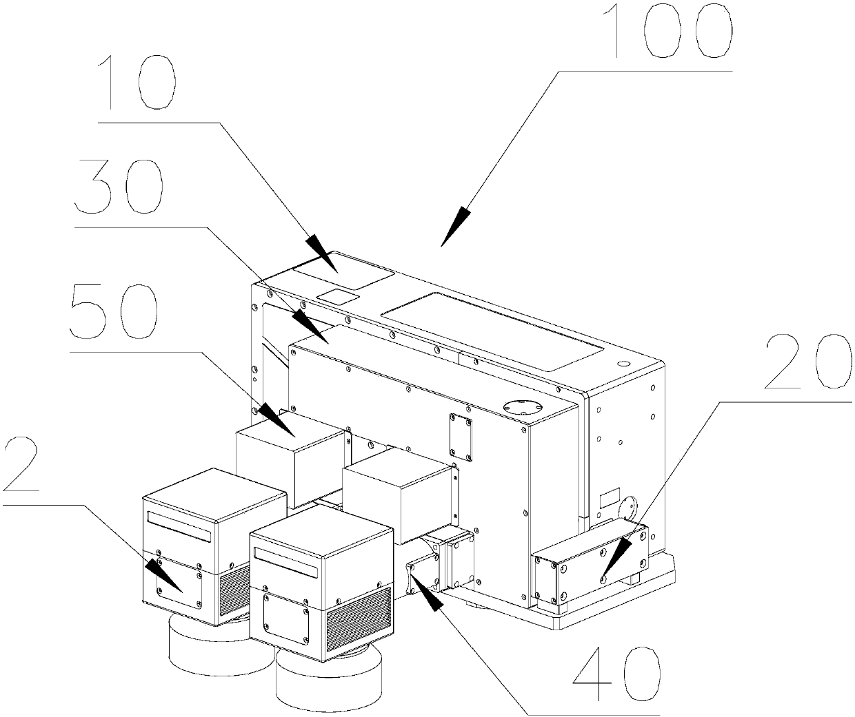
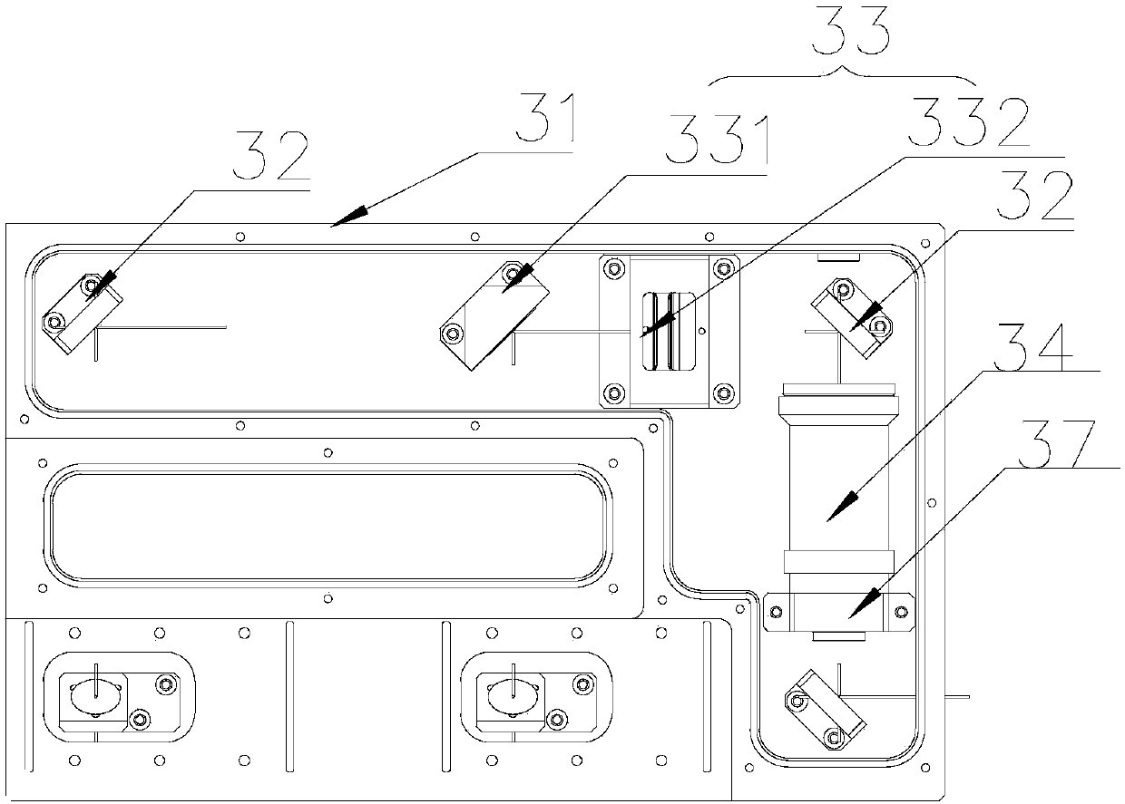
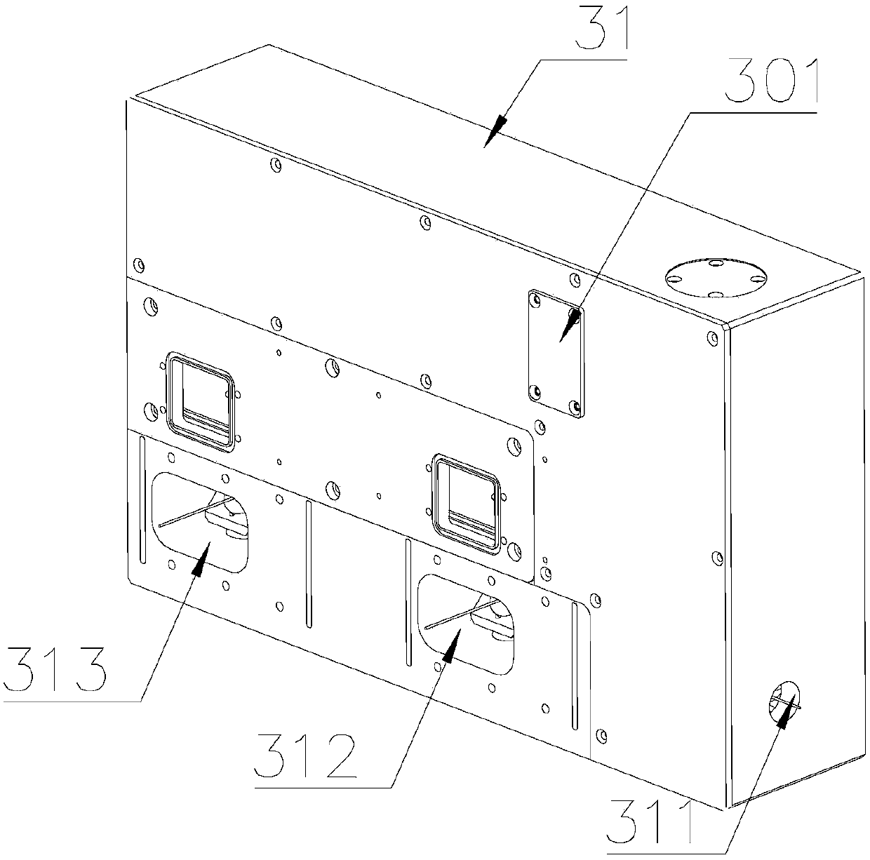
The embodiment of the invention discloses a laser light path system and a double-head laser marking machine, and relates to the technical field of laser processing equipment. The light path system comprises a laser generator, a light path input module, a light splitting module, a light path output module and a light emitting control module, the laser emitted by the laser generator is guided into the light splitting module through the light path input module, the light splitting module is used for dividing the laser into two beams, the light path output module is used for outputting the laser,the light emitting control module is used for controlling the laser in the light splitting module to pass through the light path output module. According to the provided laser light path system, a vertical light path structure is adopted, the light path input module, the light splitting module and the light path output module each are independently provided with light path structures, moreover, the light path structures communicate with one another, and the laser light path system is simple and compact in structure, high in light path stability and high in light beam quality.

Description


Claims


Application Information

Patent Timeline
Owner HANS LASER TECH IND GRP CO LTD
Learn More