
OCA optical film cutting device and cutting method

A cutting device and optical film technology, applied in laser welding equipment, welding equipment, metal processing equipment and other directions, can solve the problems of asynchronous installation at both ends of the cross bar, inaccurate cutting position, etc. Avoid the effect of inaccurate cutting positions

Inactive Publication Date: 2019-11-05
东莞艾塔极新材料科技有限公司
View PDF8 Cites 0 Cited by
  • Summary
  • Abstract
  • Description
  • Claims
  • Application Information

AI Technical Summary

Problems solved by technology

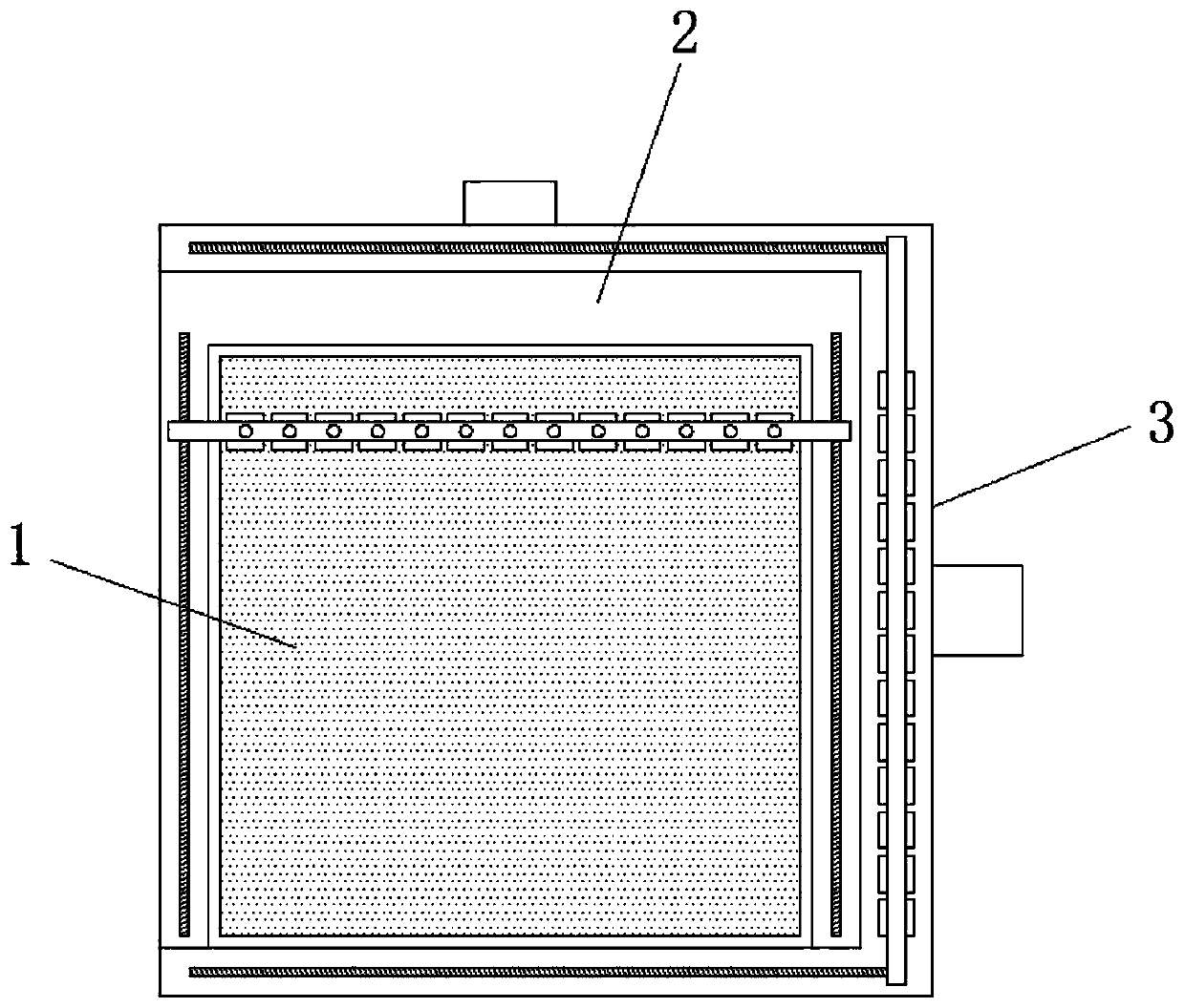
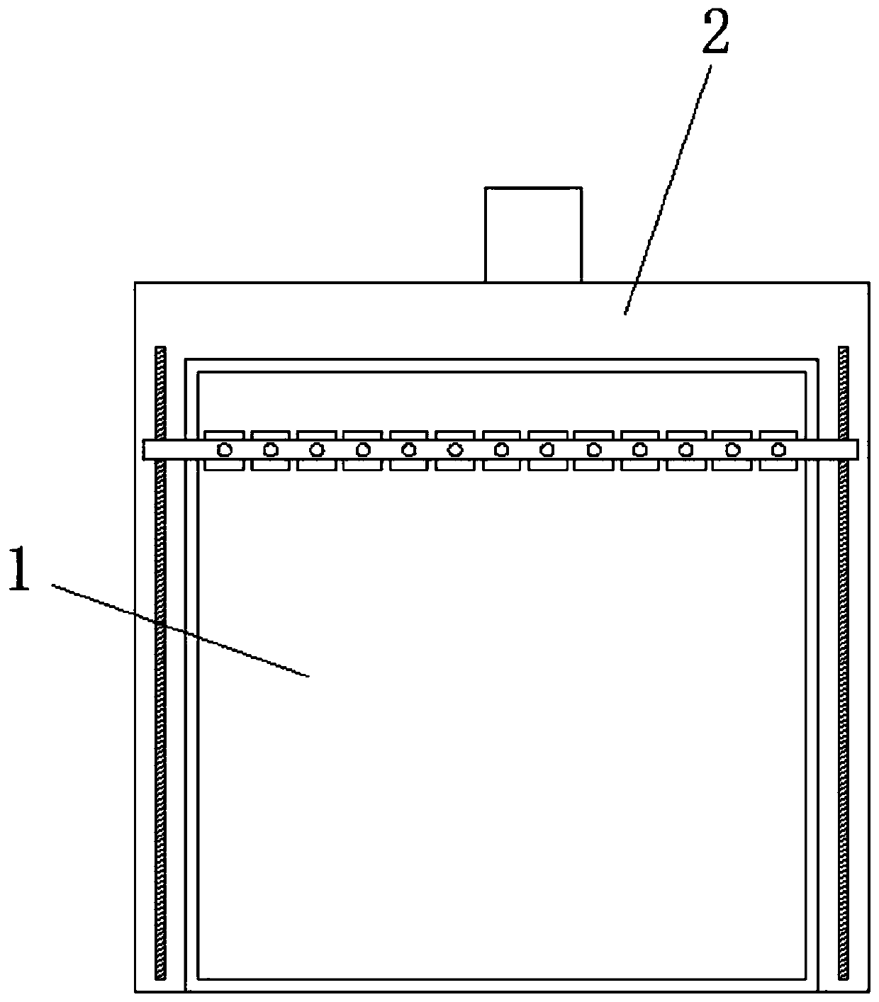
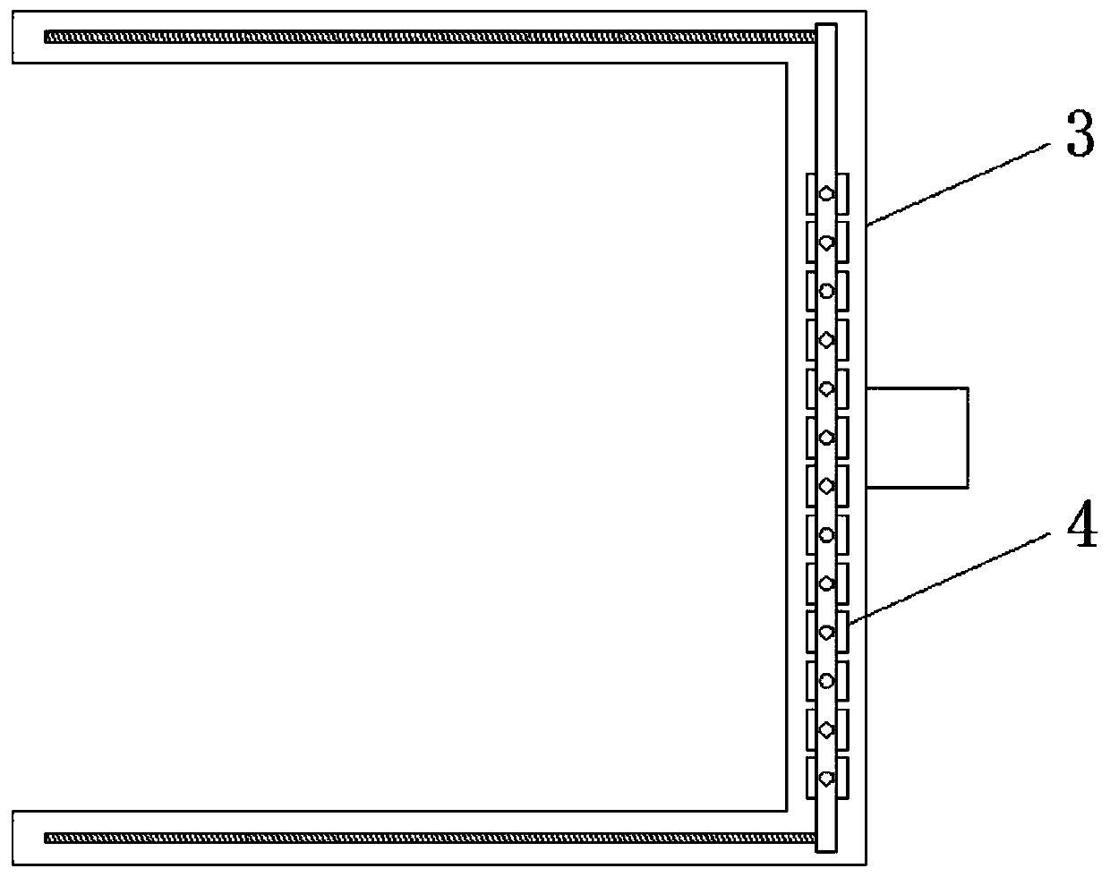
[0004] The object of the present invention is to provide a kind of OCA optical film cutting device and cutting method, aim to improve the existing OCA optical film cutting device in the use process, mostly use two different driving sources to drive the two ends of the installation cross bar, easy The two ends of the installation crossbar are not synchronized, resulting in inaccurate cutting positions and other problems

Method used


Image

  • OCA optical film cutting device and cutting method
  • OCA optical film cutting device and cutting method
  • OCA optical film cutting device and cutting method

Examples


Embodiment Construction

[0024] In order to make the purpose, technical solutions and advantages of the embodiments of the present invention clearer, the technical solutions in the embodiments of the present invention will be clearly and completely described below in conjunction with the accompanying drawings in the embodiments of the present invention. Obviously, the described embodiments It is some embodiments of the present invention, but not all of them. Based on the implementation manners in the present invention, all other implementation manners obtained by persons of ordinary skill in the art without creative efforts fall within the protection scope of the present invention. Accordingly, the following detailed description of the embodiments of the invention provided in the accompanying drawings is not intended to limit the scope of the claimed invention, but merely represents selected embodiments of the invention. Based on the implementation manners in the present invention, all other implement...


PUM


Abstract

The invention discloses an OCA optical film cutting device and cutting method. The cutting device comprises a machining table, wherein a first cutting device is arranged outside the machining table, and a second cutting device is arranged outside the first cutting device; the first cutting device is composed of a sliding block, a driving box, a mounting cross rod, a worm, a worm gear, a motor box,a servo motor, a transmission rod, a first bevel gear, a screw rod and a second bevel gear, and the structure of the second cutting device is the same as that of the first cutting device; and the whole mounting cross rod is L-shaped, clamping grooves are formed in the top end and the bottom end of the mounting cross rod correspondingly, the clamping grooves are arranged in the length direction ofthe mounting cross rod at equal intervals, and the mounting cross rod is provided with a laser mounting structure composed of a handle screw, a movable clamping block, a mounting frame and a fixed clamping block. According to the OCA optical film cutting device and the cutting method, the problems of inaccurate cutting position and the like caused by asynchronism of the two ends of the mounting cross rod are solved.

Description

technical field [0001] The invention relates to the technical field of cutting devices, in particular to an OCA optical film cutting device and a cutting method. Background technique [0002] OCA optical film is widely used in touch screens of various electronic products. During the processing of OCA optical film, it needs to be cut into small pieces that match the size of the screen according to requirements. The laser cutter is equidistantly installed on the mounting bar. [0003] The applicant of the present invention found that during the use of the existing OCA optical film cutting device and cutting method, most of them use two different driving sources to drive the two ends of the installation cross bar, which may easily cause the two ends of the installation cross bar to be out of sync. Cause the cutting position to be inaccurate. Contents of the invention [0004] The object of the present invention is to provide a kind of OCA optical film cutting device and cutt...

Claims


Application Information

Patent Timeline
IPC IPC(8): B23K26/38B23K26/402
CPCB23K26/38B23K26/402
Inventor 周智强
Owner 东莞艾塔极新材料科技有限公司
Learn More