Elevator safety circuit detection device
A safety loop and safety detection technology, applied in the field of elevators, can solve problems such as the decline in elevator reliability
- Summary
- Abstract
- Description
- Claims
- Application Information
AI Technical Summary
Problems solved by technology
Method used
Image
Examples
Embodiment 1
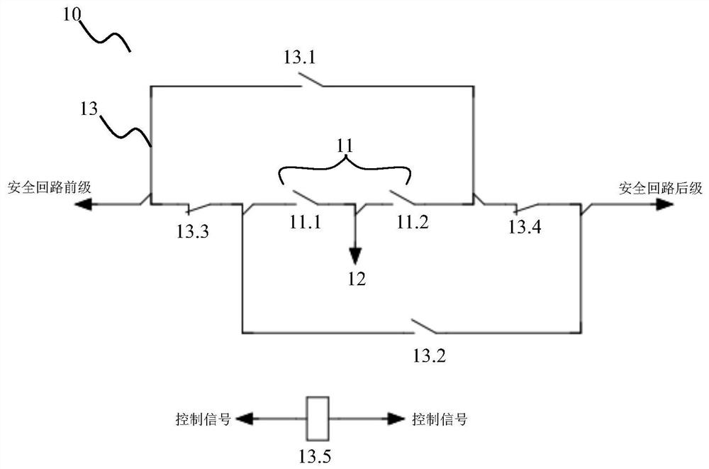
[0048] Such as image 3 As shown, this embodiment discloses a detection device for an elevator safety circuit, including an elevator safety circuit, the elevator safety circuit includes a first safety detection circuit 10, and the first safety detection circuit 10 includes a first safety switch assembly 11, The first relay circuit 13 and the first control signal.
[0049] The first safety switch assembly 11 includes a first safety switch combination 11.1 and a second safety switch combination 11.2; the first safety switch combination 11.1 is connected in series with the second safety switch combination 11.2.
[0050] The first relay circuit 13 includes a first normally open contact 13.1, a second normally open contact 13.2, a first normally closed contact 13.3, a second normally closed contact 13.4, a first relay coil 13.5, a first normally open contact 13.1 Connect in series with the first safety switch assembly 11 and then in series with the second normally open contact 13.2;...
Embodiment 2
[0061] On the basis of the first embodiment, the first safety switch combination 11.1 is a car door lock switch, and the second safety switch combination 11.2 is a floor door lock switch. Further, there may be multiple floor door lock switches.
[0062] Such as Figure 6 As shown, when the elevator arrives at the landing and opens the door, the car door lock switch and the landing door lock switch in series are disconnected at the same time, and the rear stage of the safety circuit loses voltage. At this time, it is impossible to judge whether the car door lock switch and the floor door lock switch are short-circuited respectively by the voltage of the safety circuit rear stage.
[0063] At this time, whether the car door lock switch and the landing door lock switch are normally off can be judged respectively through the first detection point and the relay.
[0064] When the first control signal controls the first relay coil 13.5 to be disconnected, the current flows as Fi...
Embodiment 3
[0067] On the basis of Embodiment 1, the first safety switch combination 11.1 is a car door lock switch on the front door connected in series with the car door lock switch on the rear door, and the second safety switch combination 11.2 is a door lock switch on the front door and a door lock switch on the rear door The switches are connected in series. Further, there may be multiple floor door lock switches.
[0068] Such as Figure 9 As shown, when the elevator arrives at the landing and opens the door, if the front door opens on this floor, then the method of Embodiment 1 can respectively detect whether the front door car door lock switch and the front door floor door lock switch are short-circuited. If the floor is opened by the rear door, then the method of Embodiment 1 can be used to detect whether the car door lock switch of the rear door and the door lock switch of the rear door floor are short-circuited.
[0069] But if the floor that the elevator arrives is when the ...
PUM
 Abstract
Description
Claims
Application Information
 - R&D
- Intellectual Property
- Life Sciences
- Materials
- Tech Scout
- Unparalleled Data Quality
- Higher Quality Content
- 60% Fewer Hallucinations
Browse by: Latest US Patents, China's latest patents, Technical Efficacy Thesaurus, Application Domain, Technology Topic, Popular Technical Reports.
© 2025 PatSnap. All rights reserved.Legal|Privacy policy|Modern Slavery Act Transparency Statement|Sitemap|About US| Contact US: help@patsnap.com


