Cylinder Safety Lock Device in Single Polishing Machine

A polishing machine and safety lock technology, applied in the mechanical field, can solve problems such as no technical solutions provided, and achieve high practical value, high stability, and high degree of automation

Active Publication Date: 2018-04-20
MORINAGA OPTICAL & ELECTRONICS EQUIP
View PDF7 Cites 0 Cited by
  • Summary
  • Abstract
  • Description
  • Claims
  • Application Information

AI Technical Summary

Problems solved by technology

[0006] However, for the formation control of the cylinder in the polishing machine, the above-mentioned patent does not provide a specific technical solution

Method used


Image

  • Cylinder Safety Lock Device in Single Polishing Machine
  • Cylinder Safety Lock Device in Single Polishing Machine
  • Cylinder Safety Lock Device in Single Polishing Machine

Examples


Embodiment Construction

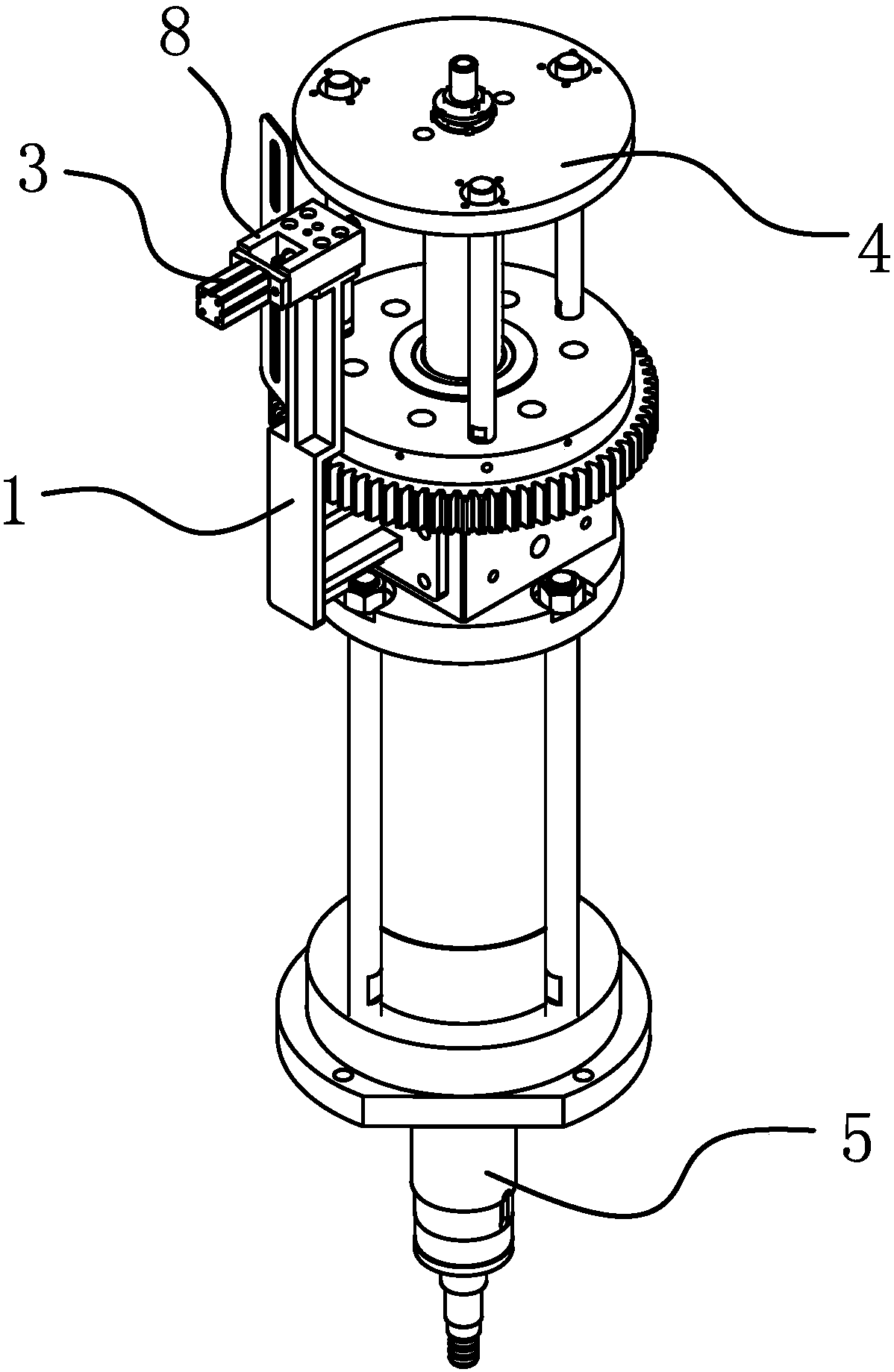
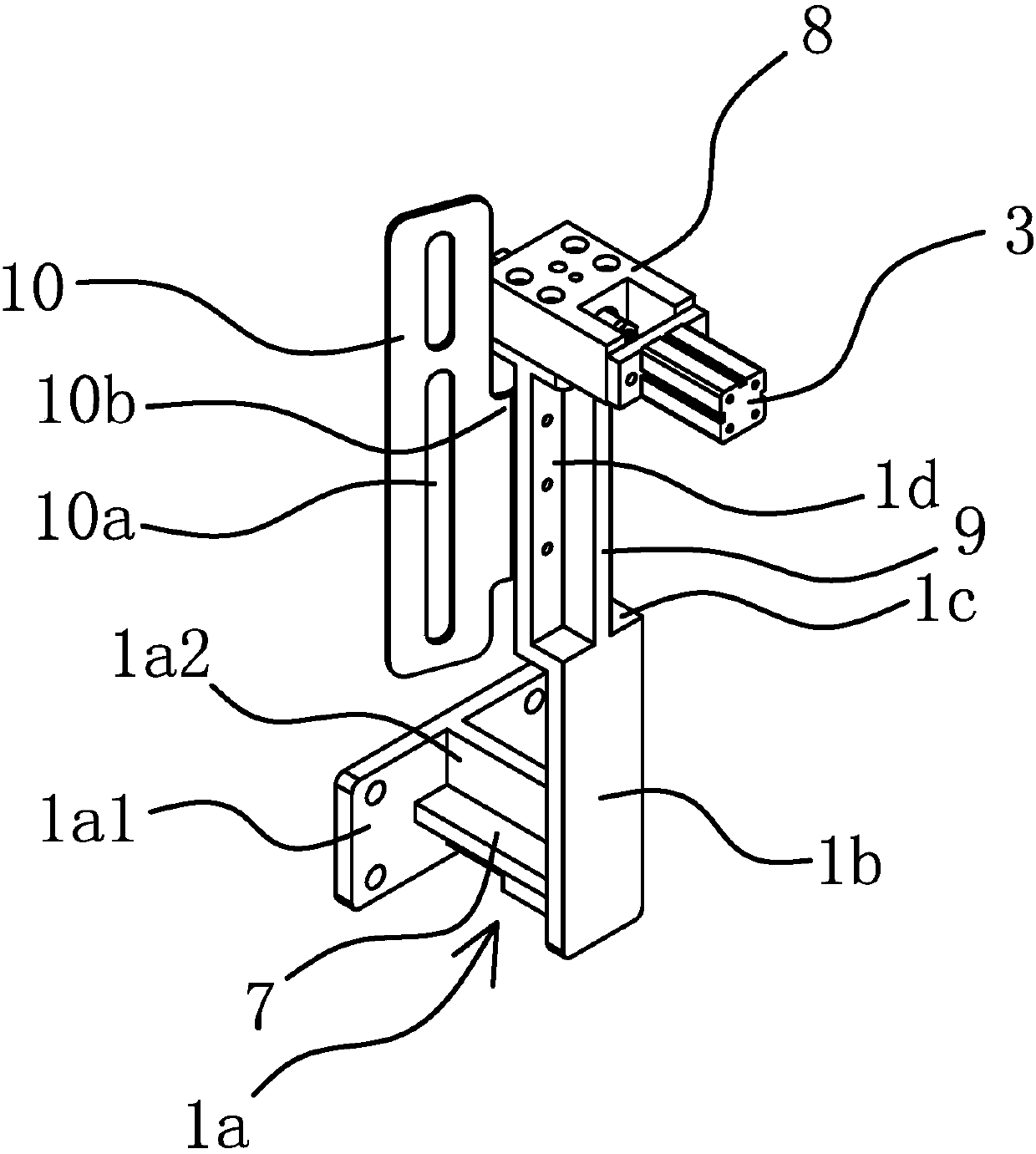
[0042] like figure 1 and figure 2 As shown, the cylinder safety lock device in the single polishing machine is arranged at the cylinder of the single polishing machine, and it includes a bracket 1, a locking rod 2, a driver 3, a pressure plate 4 and an inductor. The above-mentioned bracket 1 is in the shape of a long plate, Described support 1 is arranged in parallel with the cylinder block of cylinder and the bottom of support 1 is the connection part 1a that is used to link with cylinder, and above-mentioned locking bar 2 and driver 3 are all connected on support 1 top, and above-mentioned pressure plate 4 is used for On the cylinder shaft 5 fixedly connected to the cylinder, the inductor 6 is also connected to the support 1 and when the cylinder moves up, the inductor 6 can send a signal to make the driving part 3 act. After the driving part 3 moves, it can Drive the locking rod 2 to stretch out and block the lower part of the pressure plate 4.

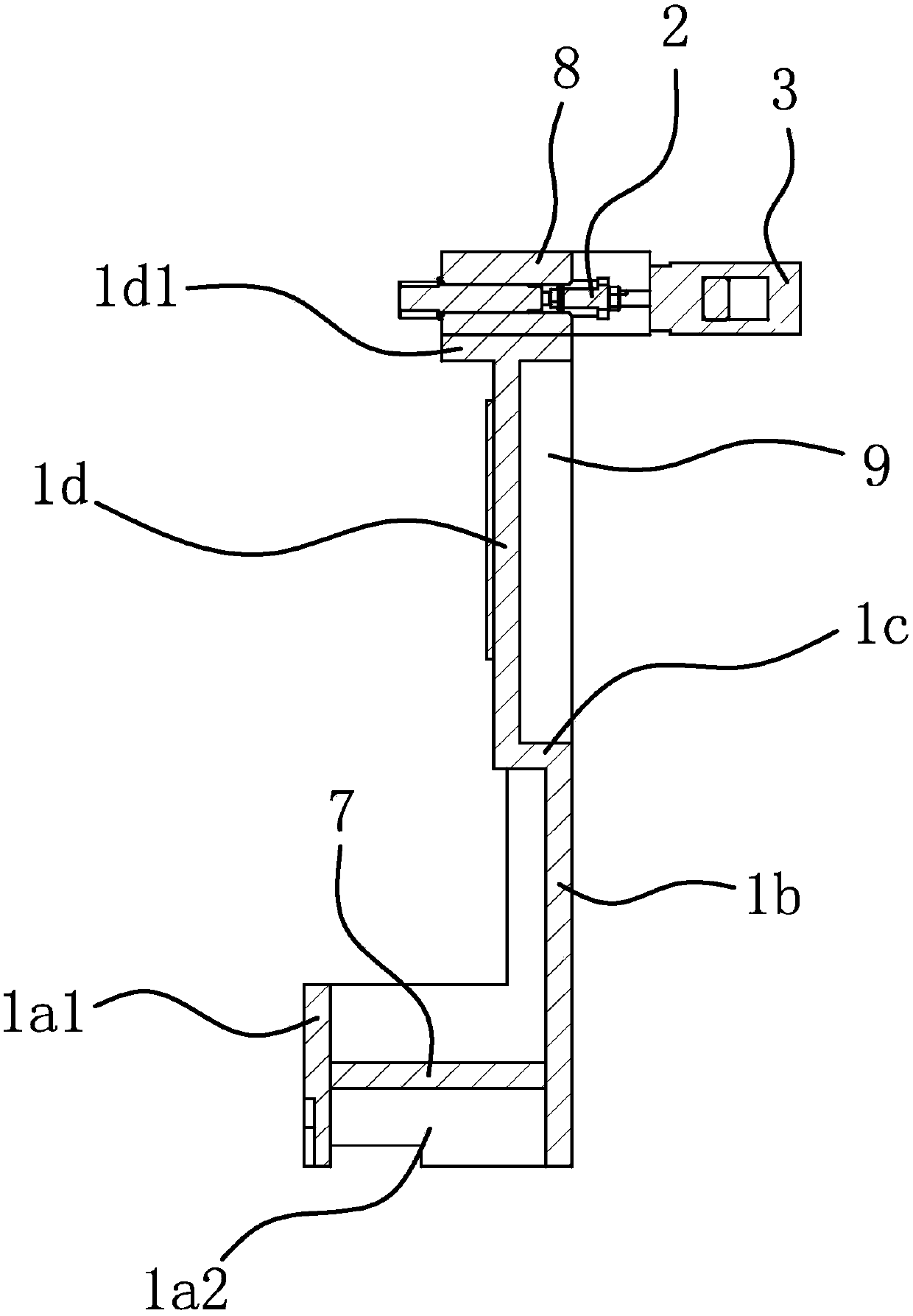
[0043] like image 3 an...


PUM


Abstract

The invention provides an air cylinder safety lock device in a single polishing machine and belongs to the technical field of machinery. The air cylinder safety lock device solves the problem of poor safety in the prior art. The air cylinder safety lock device in the polishing machine is arranged on an air cylinder of the single polishing machine. The air cylinder safety lock device comprises a support, a locking rod, a drive piece, a pressure plate and an inductor. The support is in a long plate shape. The support and a cylinder body of the air cylinder are arranged in parallel. The lower portion of the support is the connecting portion used for being connected with the air cylinder. The locking rod and the drive piece are both connected to the upper portion of the support. The pressure plate is used for being fixedly connected to an air cylinder shaft of the air cylinder. The inductor is also connected to the support and can send out a signal for driving the drive piece to act after the air cylinder moves upwards. The locking rod can be driven to extend out after the drive piece acts and blocked on the lower portion of the pressure plate. The single polishing machine with the air cylinder safety lock device is higher in safety.

Description

technical field [0001] The invention belongs to the technical field of machinery and relates to a cylinder safety lock device in a single polishing machine. Background technique [0002] Polishing machines, also known as grinders, are often used for mechanical grinding, polishing and waxing. Its working principle is: the motor drives the sponge or wool polishing disc installed on the polishing machine to rotate at high speed. Due to the joint action of the polishing disc and the polishing agent and friction with the surface to be polished, it can achieve the effect of removing paint surface pollution, oxide layer and shallow marks. Purpose. [0003] In order to realize automatic polishing, a cylinder is usually provided on the grinding machine. Because the existing grinding machine is completely controlled by the cylinder to form the stroke, the stroke of the cylinder is relatively high, which increases the cost of the entire polishing machine. [0004] The Chinese patent...

Claims


Application Information

Patent Timeline
Patent Type & Authority Patents(China)
IPC IPC(8): B24B55/00B24B29/00
CPCB24B29/00B24B55/00
Inventor 郑勇魏永利朱枫
Owner MORINAGA OPTICAL & ELECTRONICS EQUIP
Why Eureka
Try Eureka