Ceiling fan blade

A blade and ceiling fan technology, applied in the field of wind drive devices, can solve the problems of poor convenience and efficiency, inconvenient operation, time-consuming and inconvenient operation, and achieve the effect of improving operation convenience and efficiency

Active Publication Date: 2019-11-05
SUNONWEALTH ELECTRIC MACHINE IND
View PDF4 Cites 0 Cited by
  • Summary
  • Abstract
  • Description
  • Claims
  • Application Information

AI Technical Summary

Problems solved by technology

[0003] However, when assembling each blade and each safety cable, the safety cable must be threaded from the first end of the blade, passed through the channel of the blade and then positioned at the second end of the blade, which is time-consuming and inconvenient
Especially for large-scale ceiling fans, in order to maintain a cert

Method used


Image

  • Ceiling fan blade
  • Ceiling fan blade
  • Ceiling fan blade

Examples


no. 1 example

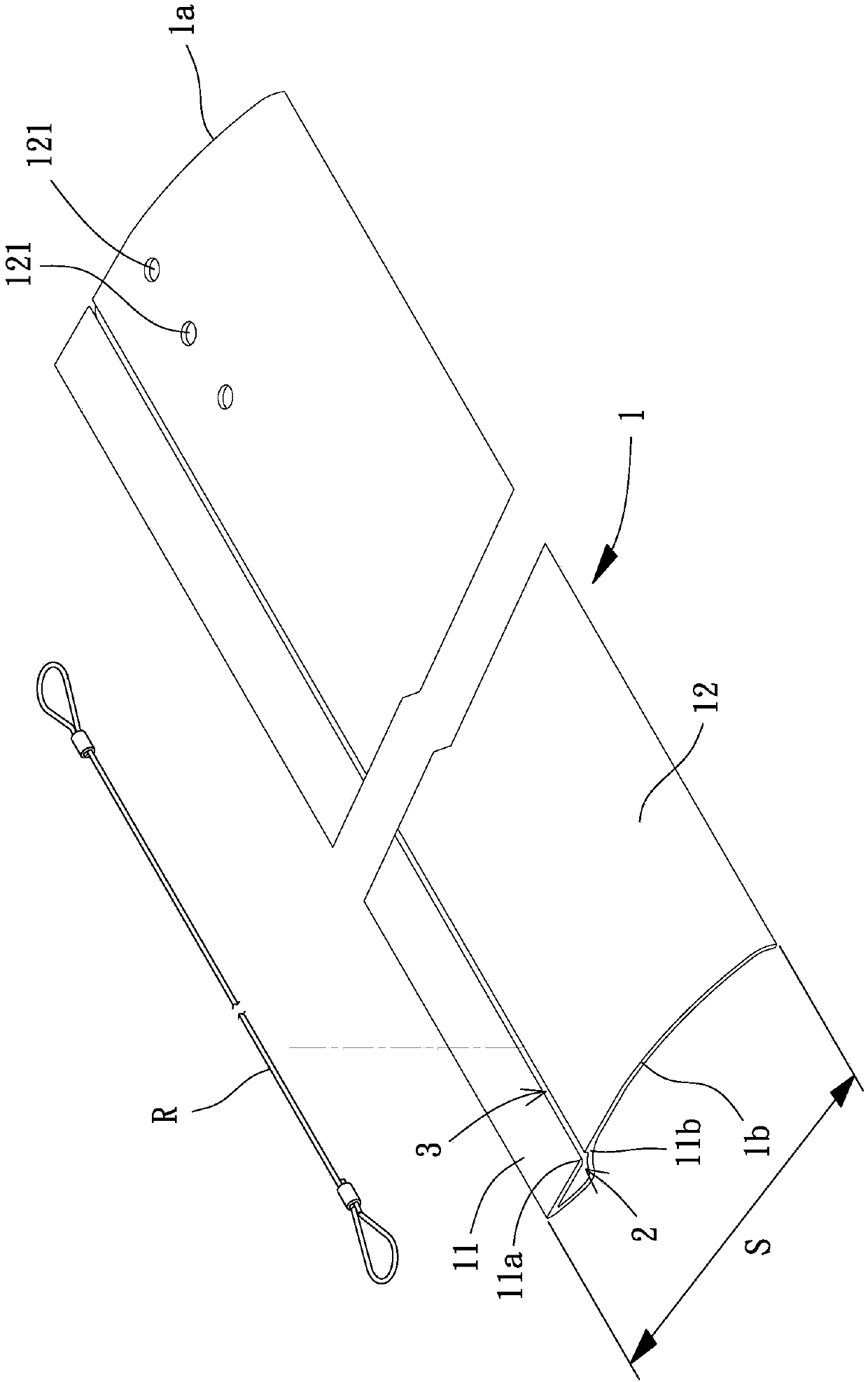
[0038] Please refer to figure 1 , the first embodiment of the ceiling fan blade of the present invention, the ceiling fan blade includes a blade body 1 , a channel 2 and a through groove 3 , the channel 2 is arranged on the blade body 1 , and the through groove 3 communicates with the channel 2 .

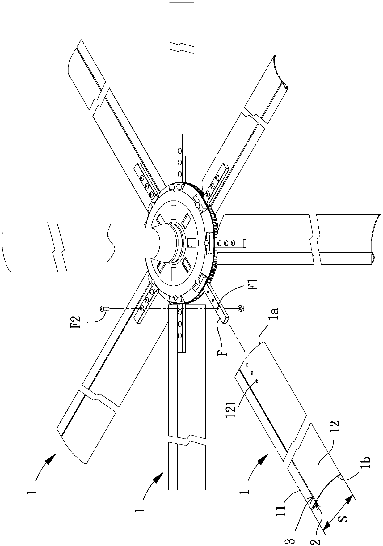
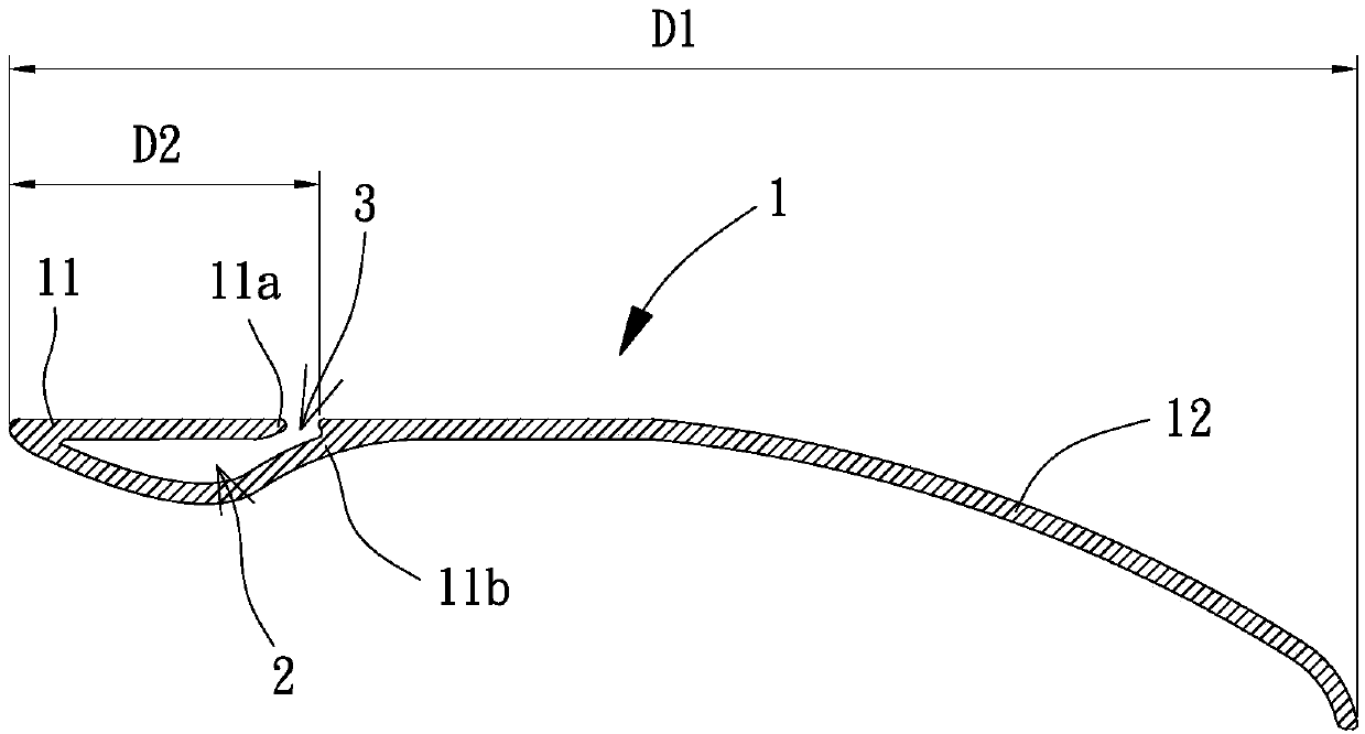
[0039] Please refer to figure 2 , 3 , the blade body 1 has a proximal end 1a and a distal end 1b opposite to each other, and the proximal end 1a can be combined with the locking bar F connected to the rotor. Specifically, the blade body 1 can be integrally formed by aluminum extrusion, and the blade body 1 can have a windward part 11 and a flow guide part 12 connected in the direction of the short side S; wherein, in the blade body 1 In the direction of the short side S, the blade body 1 has a first length D1, and the distance from the connection between the windward part 11 and the flow guide part 12 to the end of the windward part 11 away from the flow guide part 12 is a second...

no. 4 example

[0047] Please refer to Image 6 , the fourth embodiment of the ceiling fan blade of the present invention, the fourth embodiment of the present invention is substantially the same as the above-mentioned third embodiment, the main difference is that: the fourth embodiment of the present invention can also include at least one reinforcing rib 4 The at least one reinforcing rib 4 is connected to the opposite inner wall surface of the windward part 11, so that the at least one reinforcing rib 4 can be located in the channel 2; thereby, the structural strength of the windward part 11 can be further improved.

[0048] To sum up, the ceiling fan blade of the present invention uses the channel to extend from the proximal end to the distal end, and the groove communicates with the channel; when the safety cable is to be assembled on the ceiling fan blade, the groove can be used for The safety wire extends laterally, so that the safety wire can be directly inserted into the passage thro...


PUM


Abstract

A ceiling fan blade is used for solving the problem that an existing ceiling fan blade is poor in assembly convenience. The blade body is provided with a near-axis end and a far-axis end which are opposite to each other; a channel extending from the proximal end to the distal end; and the through groove is positioned on the upper side or the lower side of the blade body, extends from the near-axisend to the far-axis end, and is communicated with the channel.

Description

technical field [0001] The invention relates to a wind driving device, in particular to a ceiling fan blade. Background technique [0002] Ceiling fans have been widely used by the public because they do not occupy ground space and have a good air disturbance effect. The existing ceiling fan has a shaft, a hub, a plurality of blades and a plurality of safety cables. The hub is rotatably combined with the shaft; the plurality of blades respectively have a first end and a second end, the first end is connected to the hub, and a channel communicates between the first end and the second end The plurality of safety cables are respectively arranged in the channel of each blade, one end of each safety cable is connected to the hub, and the other end of each safety cable is positioned at the second end of each blade. Thereby, when the existing ceiling fan rotates, each safety wire can be set through, so as to prevent the blade from breaking or detaching from the hub and falling to...

Claims


Application Information

Patent Timeline
IPC IPC(8): F04D25/08F04D29/38F04D29/44
CPCF04D25/088F04D29/386F04D29/388F04D29/441
Inventor 洪银树杨坤达邱柏伟
Owner SUNONWEALTH ELECTRIC MACHINE IND
Why Eureka
Try Eureka