Clamping device for printed circuit board detection

A technology for printed circuit boards and clamping devices, which is applied in the directions of measuring devices, measuring device housings, and parts of electrical measuring instruments, etc., to achieve the effects of improving detection efficiency, high versatility, and maintaining flatness

Active Publication Date: 2019-11-05
深圳市同创精密自动化设备有限公司
View PDF10 Cites 3 Cited by
  • Summary
  • Abstract
  • Description
  • Claims
  • Application Information

AI Technical Summary

Problems solved by technology

[0004] One object of the present invention is to solve the above-mentioned problems of the existing clamping device, to provide a printed circuit board detection device that is suitable for the detection of printed circuit boards of different sizes, and can detect any point by adjusting the left and right back and forth. clamping device

Method used


Image

  • Clamping device for printed circuit board detection
  • Clamping device for printed circuit board detection
  • Clamping device for printed circuit board detection

Examples


Embodiment 1

[0024] Such as Figure 4 As shown, a clamping device for printed circuit board detection, the device includes a clamping mobile support plate 50, a front and rear moving support plate 51, a front and rear moving electric cylinder 52, a front and rear moving slide rail 53, a left and right moving support plate 54, Left and right moving electric cylinder 55 , left and right moving slide rail 56 , clamping moving plate 58 , and three clamping assemblies 59 ; The left part of moving back and forth support plate 51 is arranged on the moving part of moving electric cylinder 52 forward and backward, and the right part of moving back and forth supporting plate 51 is arranged on the slide rail 53 of front and rear movement, drives back and forth moving support plate 51 by moving electric cylinder 52 forward and backward. The front and rear moving slide rails 53 move forward and backward; the front portion of the left and right moving support plate 54 is arranged on the front portion of...

Embodiment 2

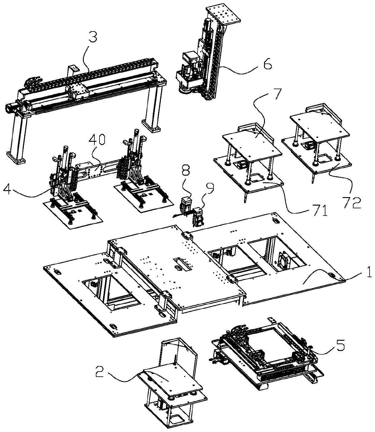
[0033] Such as figure 1 As shown, an automatic detection equipment for printed circuit boards includes a frame 1, a feeding device 2, a horizontal moving device 3, a retrieving device 4, a clamping moving device 5, a detection device 6 and a feeding device 7; the feeding device 2 is arranged at the feeding end of the frame 1, and the feeding device is used to feed the printed circuit board; the horizontal moving device 3 is arranged at the rear of the frame 1; the reclaiming device 4 is arranged on the On the horizontal moving device 3, the retrieving device 4 is used to clamp the printed circuit board, and the horizontal moving device 3 drives the printed circuit board on the reclaiming device 4 to move horizontally, and the feeding and unloading are completed through the retrieving device 4; The clamping mobile device 5 is arranged in the middle of the frame 1; the clamping mobile device 5 is used to clamp the printed circuit board and drive the printed circuit board to adju...


PUM


Abstract

The invention relates to the field of processing equipment of electronic components and discloses a clamping device for printed circuit board detection. The clamping device comprises a rack, a front-and-back movement supporting plate, a front-and-back movement electric cylinder, a front-and-back movement sliding rail, a left-and-right movement supporting plate, a left-and-right movement electric cylinder, a left-and-right movement sliding rail, a clamping movable plate and three clamping components, wherein the front-and-back movement supporting plate and the front-and-back movement electric cylinder are respectively arranged on the rack; the front-and-back movement supporting plate is arranged on the front-and-back movement electric cylinder and the front-and-back movement sliding rail; the left-and-right movement supporting plate is arranged on the front-and-back movement supporting plate through the left-and-right movement electric cylinder and the left-and-right movement sliding rail; the clamping movable plate is arranged on the left-and-right movement supporting plate and is provided with an adjustment sliding rail; and one of the three clamping components is arranged on theleft-and-right movement supporting plate, and the other two are arranged on the adjustment sliding rail. The clamping device achieves the technical effects that clamping size is convenient to adjust,and universality is high; and it is convenient to perform arbitrary point location detection during movement adjustment of a printed circuit board.

Description

technical field [0001] The invention relates to the field of processing equipment for electronic components, in particular to a clamping device for testing printed circuit boards. Background technique [0002] With the rapid advancement of the degree of electronization, the application of various electronic components is becoming more and more extensive, and the printed circuit board is a commonly used electronic component, and the printed circuit board needs to be tested during the process of processing. For example, a clamping mechanism disclosed in a Chinese invention patent whose publication number is CN204078847U and the announcement date is 2015.01.07, the clamping mechanism includes: a bracket, a clamping cylinder is arranged on the bracket, and the clamping cylinder The tail pin of the tightening cylinder is fixed on the bracket, the piston rod of the cylinder is connected with the clamping shaft through the Y-shaped joint of the cylinder, the bracket is also connect...

Claims


Application Information

Patent Timeline
Patent Type & Authority Applications(China)
IPC IPC(8): G01R1/04
CPCG01R1/0408
Inventor 王伟波鲁晓沈强益
Owner 深圳市同创精密自动化设备有限公司
Why Eureka
Try Eureka