optical lens

An optical lens and lens technology, which is applied in the field of optical lens, can solve the problem that the vehicle-mounted lens cannot have high resolution capabilities, and achieve the effects of good temperature performance, low cost, and small front port diameter

Active Publication Date: 2021-11-12
NINGBO SUNNY AUTOMOTIVE OPTECH
View PDF0 Cites 0 Cited by
  • Summary
  • Abstract
  • Description
  • Claims
  • Application Information

AI Technical Summary

Problems solved by technology

However, limited by the material of plastic, the use of a large number of plastic lenses will prevent the vehicle lens from maintaining high resolution capabilities in high and low temperature environments.

Method used


Image

  • optical lens
  • optical lens
  • optical lens

Examples


Embodiment 1

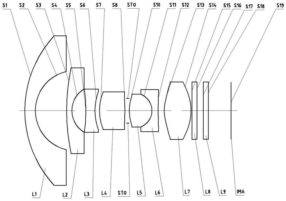
[0073] Refer to the following figure 1 An optical lens according to Embodiment 1 of the present application is described. figure 1 A schematic structural diagram of the optical lens according to Embodiment 1 of the present application is shown.

[0074] Such as figure 1 As shown, the optical lens sequentially includes a first lens L1, a second lens L2, a third lens L3, a fourth lens L4, a fifth lens L5, a sixth lens L6 and a seventh lens from the object side to the imaging side along the optical axis. Lens L7.

[0075] The first lens L1 is a meniscus lens with negative refractive power, the object side S1 is convex, and the image side S2 is concave.

[0076] The second lens L2 is a meniscus lens with negative refractive power, the object side S3 is convex, and the image side S4 is concave.

[0077] The third lens L3 is a biconcave lens with negative refractive power, and its object side S5 and image side S6 are both concave. In addition, the third lens L3 is an aspheric l...

Embodiment 2

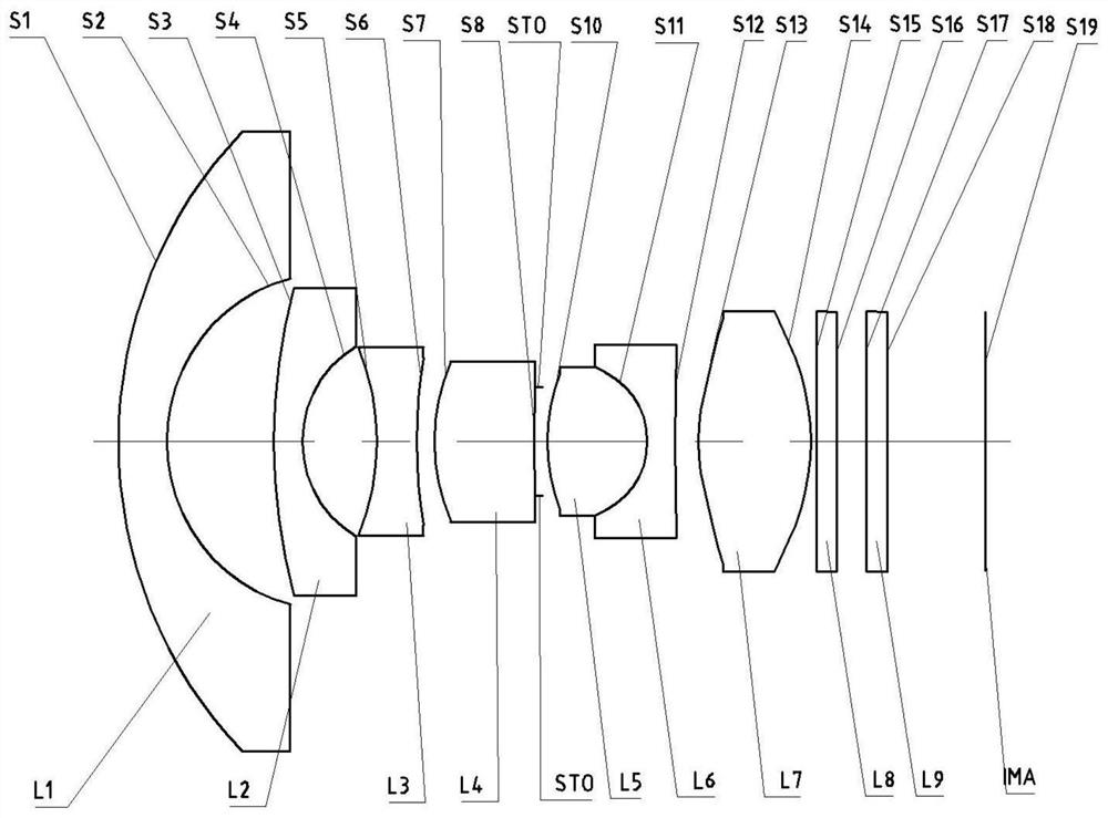
[0097] Refer to the following figure 2 An optical lens according to Embodiment 2 of the present application is described. In this embodiment and the following embodiments, for the sake of brevity, descriptions similar to those in Embodiment 1 will be omitted. figure 2 A schematic structural view of the optical lens according to Embodiment 2 of the present application is shown.

[0098] Such as figure 2 As shown, the optical lens sequentially includes a first lens L1, a second lens L2, a third lens L3, a fourth lens L4, a fifth lens L5, a sixth lens L6 and a first lens L1 from the object side to the imaging side along the optical axis. Seven lens L7.

[0099] The first lens L1 is a meniscus lens with negative refractive power, the object side S1 is convex, and the image side S2 is concave.

[0100] The second lens L2 is a meniscus lens with negative refractive power, the object side S3 is convex, and the image side S4 is concave.

[0101] The third lens L3 is a biconcav...

Embodiment 3

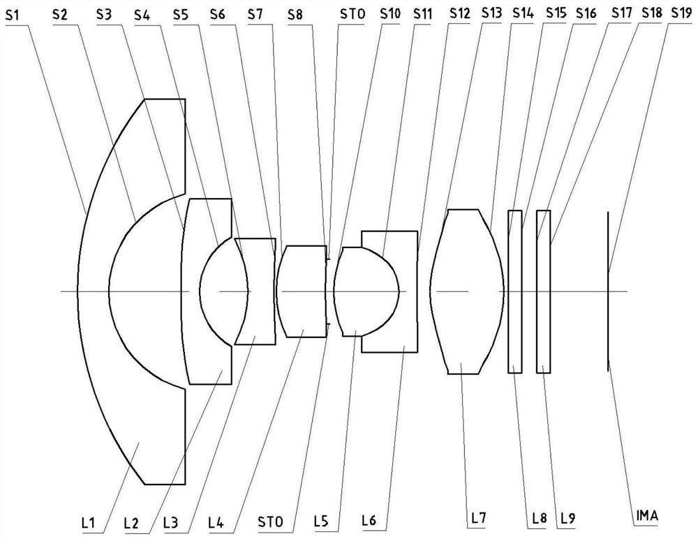
[0117] Refer to the following image 3 An optical lens according to Embodiment 3 of the present application is described. In this embodiment and the following embodiments, for the sake of brevity, descriptions similar to those in Embodiment 1 will be omitted. image 3 A schematic structural diagram of an optical lens according to Embodiment 3 of the present application is shown.

[0118] Such as image 3 As shown, the optical lens sequentially includes a first lens L1, a second lens L2, a third lens L3, a fourth lens L4, a fifth lens L5, a sixth lens L6 and a first lens L1 from the object side to the imaging side along the optical axis. Seven lens L7.

[0119] The first lens L1 is a meniscus lens with negative refractive power, the object side S1 is convex, and the image side S2 is concave.

[0120] The second lens L2 is a meniscus lens with negative refractive power, the object side S3 is convex, and the image side S4 is concave. In addition, the second lens L2 is an asp...


PUM


Abstract

The present application discloses an optical lens. The optical lens may include: a first lens, a second lens, a third lens, a fourth lens, a fifth lens, and a sixth lens in order from the object side to the image side along the optical axis. and seventh lens. Wherein, the first lens can have negative refractive power, its object side is convex, and the image side is concave; the second lens can have negative refractive power, its object side is convex, and the image side is concave; the third lens can have negative power, its object side and image side are both concave; the fourth lens may have positive power, its object side is convex; and the seventh lens may have positive power, its object side and image side are convex, wherein , the fifth lens and the sixth lens can be cemented to form a cemented lens. According to the optical lens of the present application, at least one beneficial effect of miniaturization, high resolution, low cost, good temperature performance, and small diameter at the front end can be realized.

Description

technical field [0001] The present application relates to an optical lens, and more particularly, the present application relates to an optical lens including seven lenses. Background technique [0002] The current automotive industry's requirements for automotive lenses involve miniaturization, low cost, and high resolution. At the same time, because the driving environment of the car is relatively changeable, the lens mounted outside the car must have the ability to maintain a high resolution in various harsh environments. [0003] However, with the gradual use of large-size, high-pixel chips, the original pixels of vehicle lenses can no longer match these chips, and it is urgent to develop new higher-pixel lenses to replace existing low-pixel lenses on the market. In order to achieve a higher pixel of the lens, it is necessary to increase the number of lenses or use aspherical lenses, which are limited by the two requirements of low cost and miniaturization. [0004] In...

Claims


Application Information

Patent Timeline
Patent Type & Authority Patents(China)
IPC IPC(8): G02B13/00G02B13/18
CPCG02B13/0045
Inventor 王东方陈雨曦姚波
Owner NINGBO SUNNY AUTOMOTIVE OPTECH
Why Eureka
Try Eureka