Eureka AIR delivers breakthrough ideas for toughest innovation challenges, trusted by R&D personnel around the world.

Film switch assembly machine and film switch production process

A membrane switch and assembly machine technology, applied in the direction of electrical switches, electrical components, circuits, etc., can solve the problems of loss of conduction and connection function of products, poor adhesion of keys, affecting product quality, etc., to solve problems such as poor adhesion of keys, Novel design and strong practical effect

Pending Publication Date: 2019-11-05
东莞市谊嘉电子科技有限公司
View PDF0 Cites 0 Cited by
  • Summary
  • Abstract
  • Description
  • Claims
  • Application Information

AI Technical Summary

Problems solved by technology

[0002] During the assembly process of the membrane tact switch, it is necessary to use a membrane to fix the dome (metal shrapnel) of the switch on the switch base, and then stick the dot-shaped buttons on the membrane. This method of assembly is prone to sticking of the buttons. Serious defects such as tightness, deviation of the installation position of the button, and easy drop of the button during assembly cause the product to lose the conduction connection function, resulting in a high defect rate of the switch, and at the same time, the consistency of the product is poor, which affects the quality of the product; therefore, It is necessary to design an assembly machine for membrane tact switches to improve the production yield of membrane tact switches and improve the quality of membrane tact switches

Method used


Image

  • Film switch assembly machine and film switch production process
  • Film switch assembly machine and film switch production process
  • Film switch assembly machine and film switch production process

Examples


Embodiment Construction

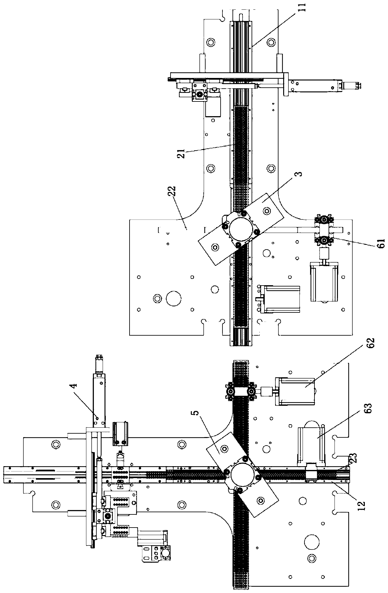
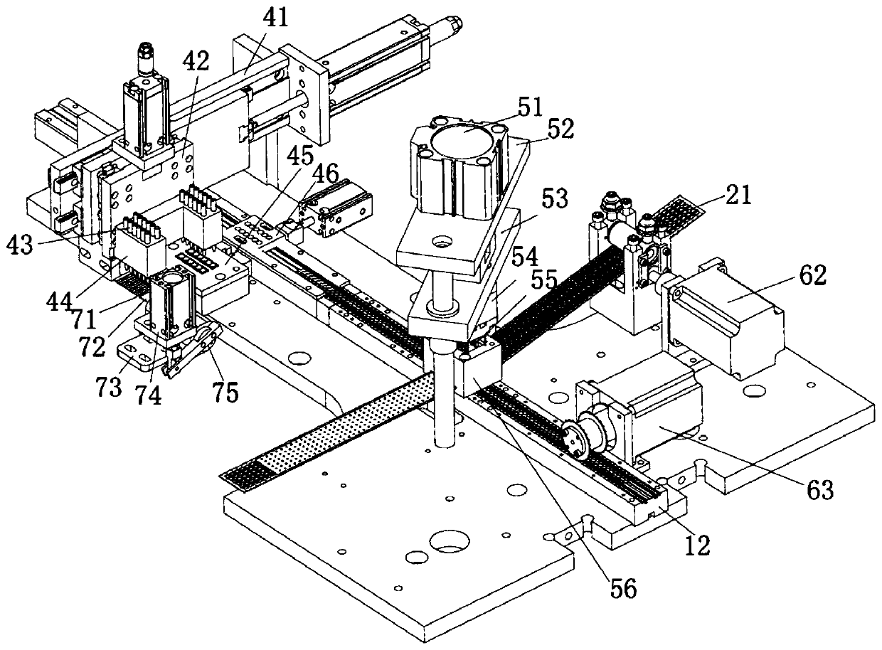
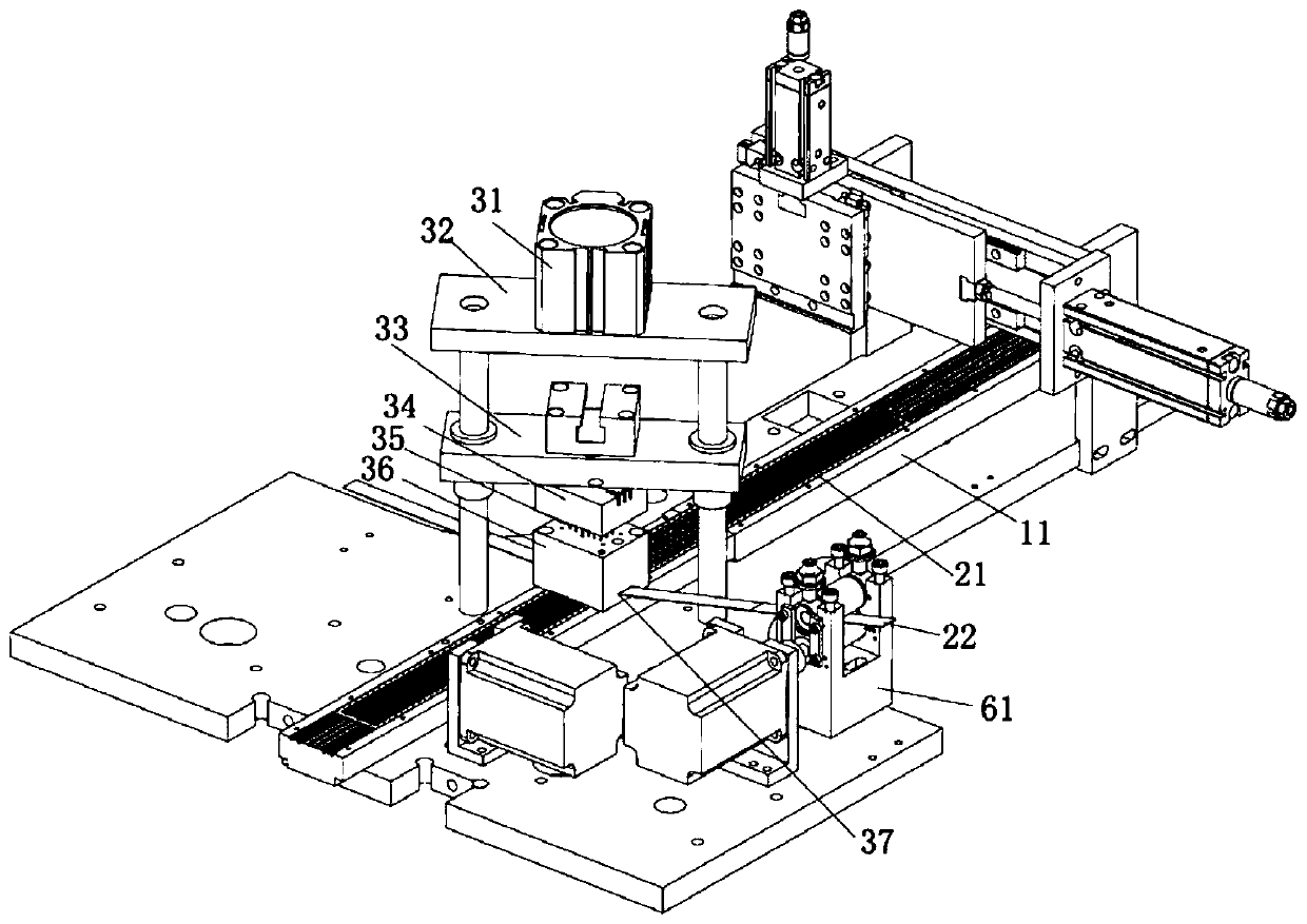
[0027] The present invention will be described in further detail below in conjunction with the accompanying drawings.

[0028] The embodiments described by referring to the figures are exemplary and are intended to explain the present application and should not be construed as limiting the present application. In the description of the present application, it should be understood that the terms "center", "longitudinal", "transverse", "length", "width", "thickness", "upper", "lower", "front", " Orientation or position indicated by "back", "left", "right", "vertical", "horizontal", "top", "bottom", "inner", "outer", "clockwise", "counterclockwise", etc. The relationship is based on the orientation or positional relationship shown in the drawings, and is only for the convenience of describing the application and simplifying the description, rather than indicating or implying that the device or element referred to must have a specific orientation, be constructed and operated in a ...


PUM


Abstract

The invention discloses a film switch assembly machine and a film switch production process. The film switch assembly machine includes a machine which is equipped with a first material rail and a second material rail. The first material rail is used for conveying a film carrying material belt, and the second material rail is used for conveying a base material belt. The first material rail is equipped with a point-pasting device for pasting keys onto the film carrying material belt. The second material rail is equipped with a discharging device and a film pasting device. The discharging deviceis used for moving and placing spring pieces on corresponding bases of the base material belt. The film pasting device punches the film carrying material belt and the keys into patches and pasting thepatches onto the corresponding bases of the base material belt. The film carrying material belt includes a carrier belt and a film. The carrier belt is provided with a carrying area in the middle, and the carrying area is provided with a plurality of type holes distributed in a matrix. The film is glued to one side of the carrying area. The point-pasting device cuts a hard material belt into a plurality of dot-shaped keys and pastes the keys onto the film under the corresponding type holes. By fixing the keys above the spring pieces through the film, problems such as insecure adhesion and installation position deviation of keys are solved, the product yield is improved, and the benefits of enterprises are improved.

Description

technical field [0001] The invention relates to the technical field of production of miniature light-touch membrane switches, in particular to a membrane switch assembly machine and a membrane switch production process. Background technique [0002] During the assembly process of the membrane tact switch, it is necessary to use a membrane to fix the dome (metal shrapnel) of the switch on the switch base, and then stick the dot-shaped buttons on the membrane. This method of assembly is prone to sticking of the buttons. Serious defects such as tightness, deviation of the installation position of the button, and easy drop of the button during assembly cause the product to lose the conduction connection function, resulting in a high defect rate of the switch, and at the same time, the consistency of the product is poor, which affects the quality of the product; therefore, It is necessary to design an assembly machine of a membrane tact switch to improve the production yield of t...

Claims


Application Information

Patent Timeline
Patent Type & Authority Applications(China)
IPC IPC(8): H01H11/00H01H13/88
CPCH01H11/00H01H13/88
Inventor 孙传松
Owner 东莞市谊嘉电子科技有限公司
Why Eureka
Eureka Blog
Learn More