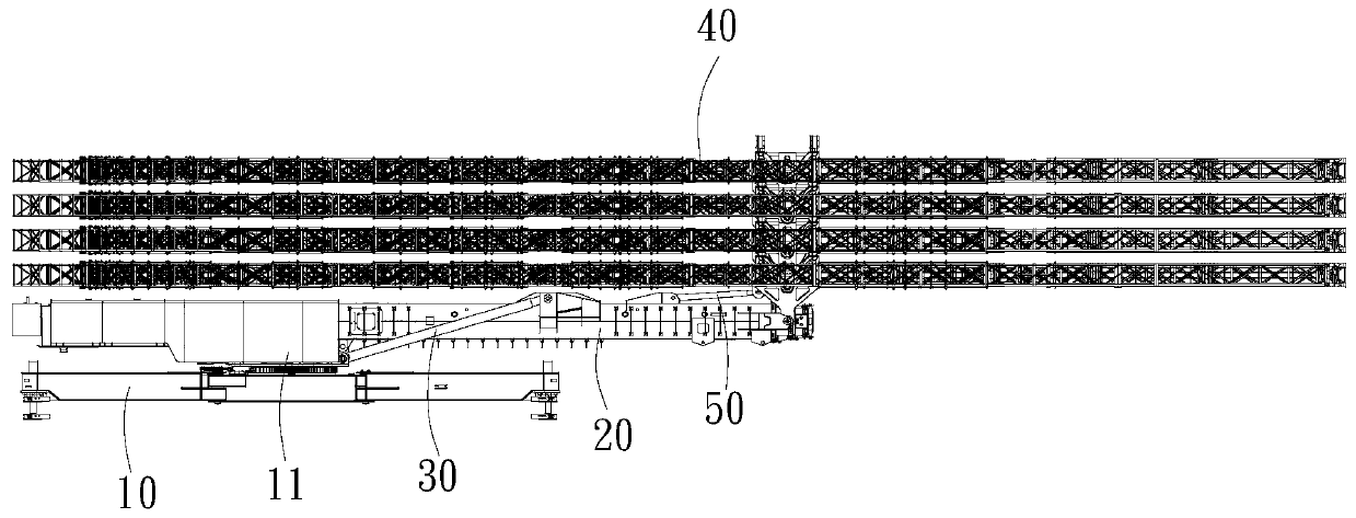
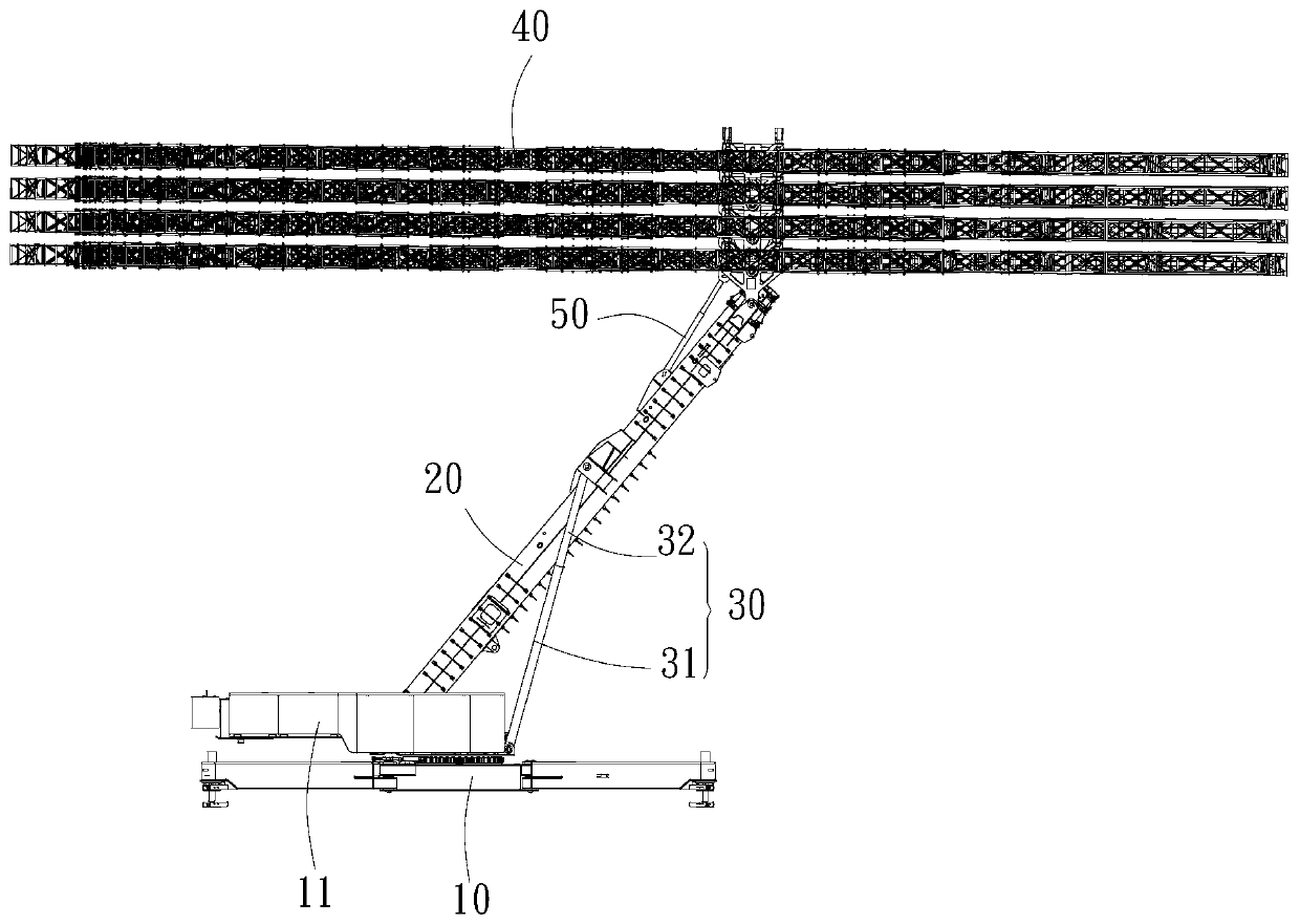
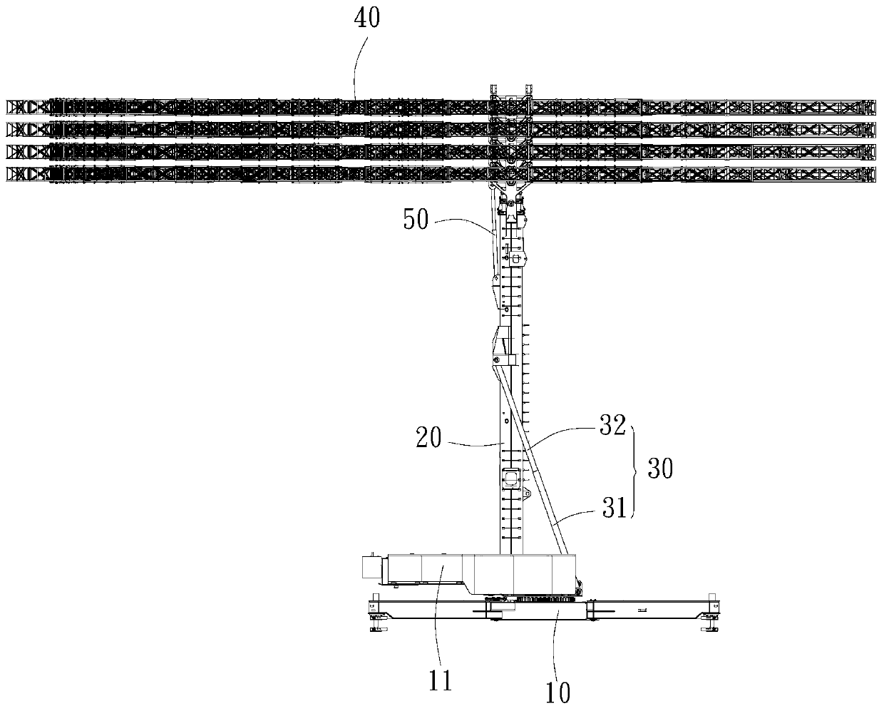
Antenna lifting control device and control method

A lifting control and antenna technology, applied in the direction of antenna support/installation device, antenna, antenna parts, etc.

Active Publication Date: 2019-11-05
SHENZHEN WAVE TELECOMM TECH CO LTD
View PDF10 Cites 4 Cited by
  • Summary
  • Abstract
  • Description
  • Claims
  • Application Information

AI Technical Summary

Problems solved by technology

[0004] Based on this, it is necessary to provide an antenna lifting control de

Method used


Image

  • Antenna lifting control device and control method
  • Antenna lifting control device and control method
  • Antenna lifting control device and control method

Examples


Embodiment Construction

[0036] In order to facilitate the understanding of the present invention, the following will describe the present invention more fully. However, the present invention can be embodied in many different forms and is not limited to the embodiments described herein. On the contrary, these embodiments are provided to make the understanding of the disclosure of the present invention more thorough and comprehensive.

[0037] Unless otherwise defined, all technical and scientific terms used herein have the same meaning as commonly understood by one of ordinary skill in the technical field of the invention. The terms used herein in the description of the present invention are for the purpose of describing specific embodiments only, and are not intended to limit the present invention.

[0038] It should be noted that when an element is referred to as being “fixed” to another element, it can be directly on the other element or there can also be an intervening element. When an element i...


PUM

PropertyMeasurementUnit
Rotation rangeaaaaaaaaaa

Abstract

The invention relates to an antenna lifting control device and control method. The antenna lifting control device includes a support platform, a lifting arm hinged to the support platform at one end,a lifting arm driving mechanism hinged to the support platform and the lifting arm at the two ends respectively, an antenna hinged to one end, away from the support platform, of the lifting arm, and an antenna driving mechanism hinged to the lifting arm and the antenna at the two ends respectively. According to the antenna lifting control device, the lifting arm driving mechanism extends or contracts to drive the lifting arm to rotate relative to the support platform so as to drive the antenna to rise or fall, the antenna driving mechanism extends or contracts to drive the antenna to rotate relative to the lifting arm, and the direction of rotation of the antenna driven by the antenna driving mechanism is opposite to the direction of rotation of the lifting arm driven by the lifting arm driving mechanism. Thus, the center of gravity of the antenna does not change dramatically in the rising and falling process of the antenna in bad environments, overall shaking caused by dramatic changeand the influence of dramatic change on the life of the antenna or mechanism are avoided, and the rising and falling process of the antenna can be stable, safe and reliable.

Description

technical field [0001] The invention relates to the technical field of communication equipment, in particular to an antenna lifting control device and a control method. Background technique [0002] The short-wave antenna refers to the transmitting or receiving antenna working in the short-wave band (3-30MHz). Shortwave mainly uses ionospheric reflection propagation for communication, so it is not restricted by network hubs and relay conditions, and is one of the important means of modern long-distance radio communication. Usually, the lower the frequency, the larger the size of the antenna. The maximum size of a large-scale short-wave antenna can reach 50 meters, and the distance between the antenna and the ground is required to be farther. Generally, the short-wave antenna requires a minimum distance of 12.5 meters from the ground, and requires no any covering. [0003] Considering the large size of the short-wave antenna and its height from the ground, the inconvenience...

Claims


Application Information

Patent Timeline
IPC IPC(8): H01Q1/12H01Q3/04
CPCH01Q1/1235H01Q3/04
Inventor 陈诗桓张少林
Owner SHENZHEN WAVE TELECOMM TECH CO LTD
Why Eureka
Try Eureka