Aluminum casting motor casting equipment

A casting equipment and aluminum casting technology, applied in the field of aluminum casting motor casting equipment, can solve the problems of slow cooling rate, reduced production rate, low product forming rate, etc., and achieve the effects of convenient use, improved product quality, and improved product forming rate.

Inactive Publication Date: 2019-11-08
中擎电机有限公司
View PDF14 Cites 3 Cited by
  • Summary
  • Abstract
  • Description
  • Claims
  • Application Information

AI Technical Summary

Problems solved by technology

[0002] At present, in the production of aluminum cast motors, the motor housing needs to be cast and formed, and casting molds are used in casting. At this stage, casting is usually done by pouring molten raw materials. However, during casting, due to the high internal temperature of the mold and the cooling rate It is slower, which makes the product molding rate low, reduces the production rate, and the distribution of raw materials in the cavity is not uniform enough, which will lead to a decrease in product quality. For this reason, an aluminum casting motor casting equipment is designed to solve the above problems

Method used


Image

  • Aluminum casting motor casting equipment
  • Aluminum casting motor casting equipment
  • Aluminum casting motor casting equipment

Examples


Embodiment 1

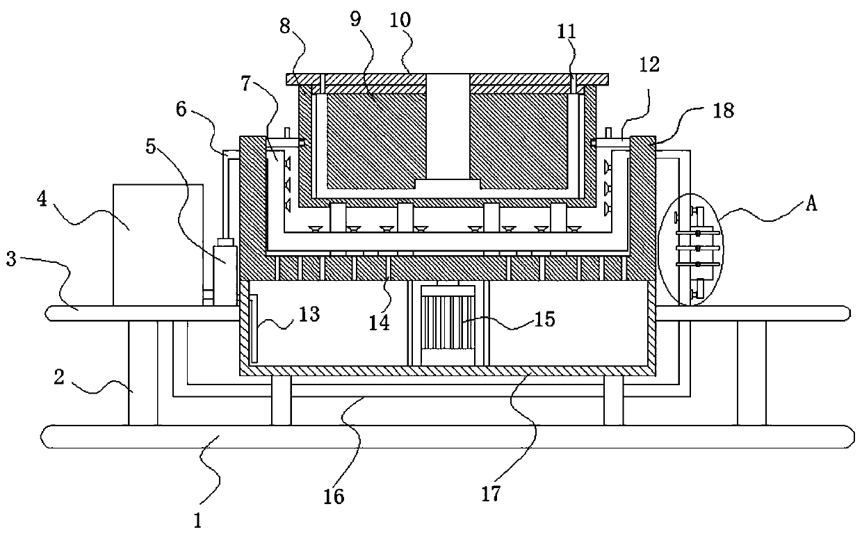
[0029] see Figure 1-3 , an aluminum casting motor casting equipment, including a bottom plate 1, a horizontal plate 3, a base 17, a rotary seat 18, a lower mold 8, a mold core 9, and an upper template 10, and the horizontal plate 3 is horizontally fixed on the bottom plate 1 through a support column 2 Above, the base 17 is fixed on the horizontal plate 3, and the revolving seat 18 is movable above the base 17, and the motor 15 that drives the revolving seat 18 to rotate is fixed in the base 17.

[0030] The top of the revolving seat 18 is open, the revolving seat 18 is detachably provided with a lower mold 8, the top of the lower mold 8 is provided with an upper template 10, the bottom surface of the upper template 10 is fixed with a mold core 9, and the mold core 9 and the lower mold 8 A mold cavity is formed between them, and a heat dissipation gap is left between the outer wall of the lower mold 8 and the inner wall of the rotary seat 18, and drain holes 14 are distributed...

Embodiment 2

[0042] see Figure 4The opening of the rotary seat 18 is provided with a positioning mechanism for fixing the lower mold 8, and the positioning mechanism includes an annular fixed plate 12, the fixed plate 12 is fixed on the open inner wall of the rotary seat 18, and the top of the fixed plate 12 Notches are distributed in the circumferential direction of the surface, and the side of the fixed plate 12 is provided with several through holes corresponding to the notches. A slider 25 sliding along its length direction is arranged in the notch, and the bottom surface of the slider 25 is connected to the bottom surface of the notch. A gap is left, and a threaded hole is longitudinally provided in the slide block 25, and a positioning bolt 27 is spirally arranged at the threaded hole, and a positioning pin 26 is slidably arranged in the through hole, and the inner end of the positioning pin 26 is fixed with the slide block 25, and the end of the positioning pin 26 Out of the throug...


PUM


Abstract

The invention discloses aluminum casting motor casting equipment which comprises a bottom plate, a transverse plate, a base, a rotary seat, a lower die, a die core and an upper die plate. The transverse plate is horizontally fixed above the bottom plate through a supporting column, the base is fixed on the transverse plate, the rotary seat is movably arranged above the base, a motor for driving the rotary seat to rotate is fixed in the base, the top end of the rotary seat is opened, the lower die is detachably arranged in the rotary seat, the upper die plate is arranged above the lower die, the die core is fixed on the bottom surface of the upper die plate, a cavity is formed between the die core and the lower die, a heat dissipation gap is reserved between the outer wall of the lower dieand the inner wall of the rotary seat, draining holes are distributed at the bottom of the shell of the rotary seat, a cooling water channel is arranged in the heat dissipation gap, and a plurality ofatomizing nozzles are distributed on the cooling water channel. According to the aluminum casting motor casting equipment, raw materials can be uniformly distributed in the cavity by rotating the rotary seat, and the cooling water channel and the atomizing nozzles are arranged, so that products in the cavity can be rapidly cooled, and product forming is accelerated.

Description

technical field [0001] The invention relates to the field of motor production, in particular to casting equipment for aluminum casting motors. Background technique [0002] At present, in the production of aluminum cast motors, the motor housing needs to be cast and molded. Casting molds are used in casting. At this stage, casting is usually done by pouring molten raw materials. However, during casting, due to the high internal temperature of the mold and the cooling rate It is slower, which makes the product molding rate low, reduces the production rate, and the distribution of raw materials in the cavity is not uniform enough, which will lead to a decrease in product quality. For this reason, an aluminum casting motor casting equipment is designed to solve the above problems. Contents of the invention [0003] The object of the present invention is to provide an aluminum casting motor casting equipment to solve the problems raised in the above-mentioned background techno...

Claims


Application Information

Patent Timeline
Patent Type & Authority Applications(China)
IPC IPC(8): B22D13/00B22D13/10
CPCB22D13/00B22D13/105
Inventor 林波叶灵荣林娜金新兵叶云兰
Owner 中擎电机有限公司
Why Eureka
Try Eureka