
Electric material beating device

A feeder and electric technology, applied in the field of 3D printing, can solve the problems of poor quality of printed parts, difficulty in stress release, etc., and achieve the effect of high product performance, high matching tightness, and increased interlayer bonding force

Pending Publication Date: 2019-11-08
上海酷鹰机器人科技有限公司
View PDF0 Cites 1 Cited by
  • Summary
  • Abstract
  • Description
  • Claims
  • Application Information

AI Technical Summary

Problems solved by technology

[0004] In view of the difficulty in stress release in the existing printing technology, which leads to poor quality of printed parts, the invention provides an electric beater, which can increase the bonding force between layers, stabilize the shape of the extruded melt, and beat at high frequency It has the function of auxiliary stress relief

Method used


Image

  • Electric material beating device
  • Electric material beating device
  • Electric material beating device

Examples


Embodiment Construction

[0031] The following will clearly and completely describe the technical solutions in the embodiments of the present invention with reference to the accompanying drawings in the embodiments of the present invention. Obviously, the described embodiments are only some, not all, embodiments of the present invention. Based on the embodiments of the present invention, all other embodiments obtained by persons of ordinary skill in the art without making creative efforts belong to the protection scope of the present invention.

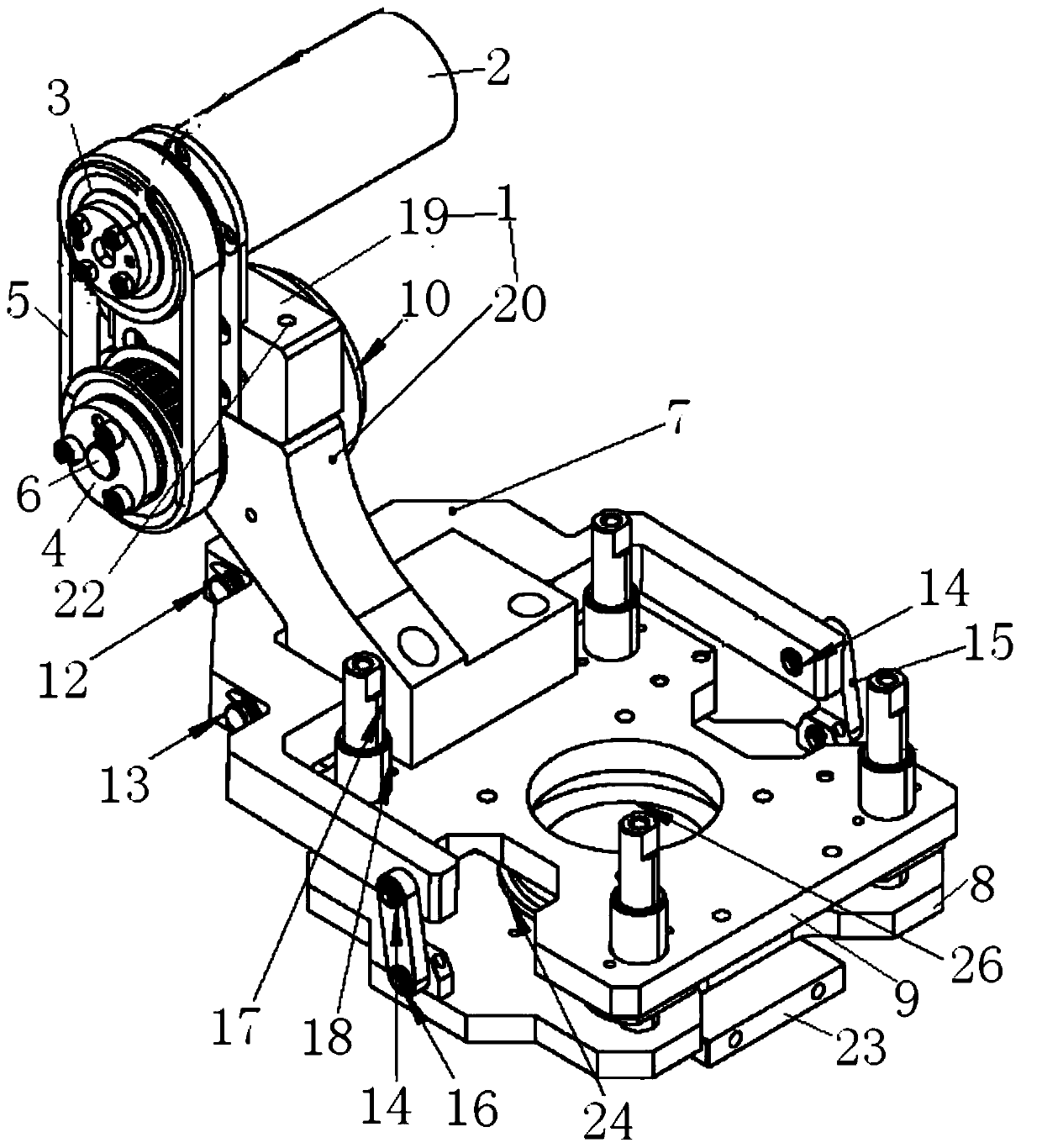
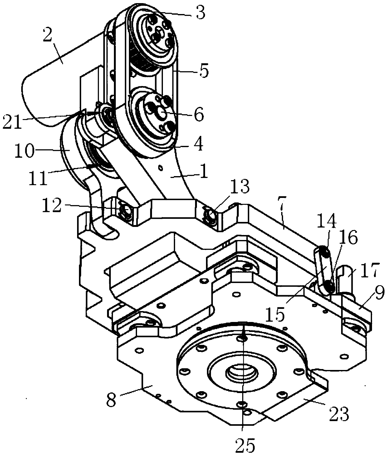
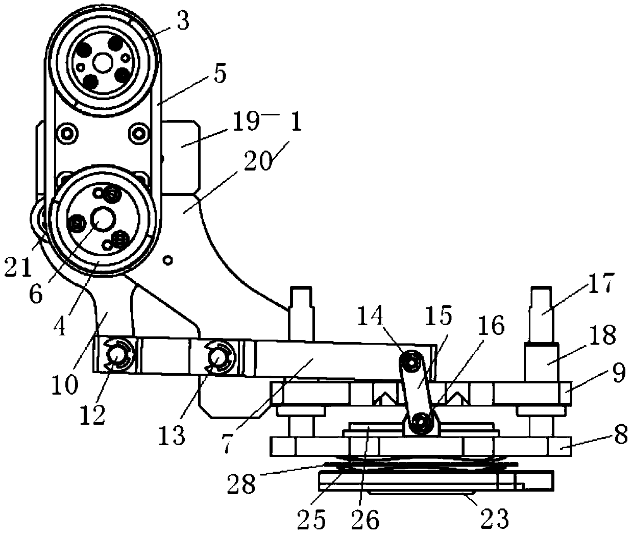
[0032] As an embodiment of the present invention, an electric beater includes a driving device and a beating device, see figure 1 and figure 2 .

[0033] Wherein, the driving device comprises a transmission part support 1, a motor 2, a driving wheel 3 and a driven wheel 4, the shafts of the driving wheel 3 and the driven wheel 4 are fixed on the top of the transmission part support 1, the driving wheel 3 shafts are connected with the motor 2, and the driving...


PUM


Abstract

The invention discloses an electric material beating device. The electric material beating device comprises a driving device and a beating device; in the driving device, a shaft of a driving wheel anda shaft of a driven wheel are fixed on the upper part of a transmission part support, and the shaft of the driven wheel is an eccentric shaft; in the beating device, and two branches of a Y-shaped connecting rod are located on the two sides of a fixed base; the bottom of the transmission part support is connected with the fixed base, the shaft of the driven wheel is rotatably connected with a rocker, the bottom of the rocker is rotationally fixed at the end of the Y-shaped connecting rod through a first rotating shaft, the middle of the Y-shaped connecting rod is rotationally fixed on the transmission part support through a second rotating shaft, the ends of two branches of the Y-shaped connecting rod are rotatably connected to one end of a first connecting rod through two third rotatingshafts, and the other end of the first connecting rod is rotatably connected to two sides of a movable bottom plate through a fourth rotating shaft, the movable bottom plate is positioned below the fixed base, and a material beating unit is arranged inside a through hole in the middle of the movable bottom plate. According to the electric material beating device, the curve movement is converted into linear movement, and high-frequency beating of materials can be realized.

Description

technical field [0001] The invention belongs to the technical field of 3D printing, and in particular relates to an electric beater. Background technique [0002] Traditional products have to go through a long cycle from design to production and waste a lot of materials, while 3D printing technology integrates product design and printing manufacturing, and can produce products with complex structures in a few hours or a few days. Moreover, the materials used in 3D printing technology are mainly PLA, ABS or metal materials, which have almost no material loss, which greatly reduces production costs and creates conditions for enterprises to increase profits. 3D printing technology has the advantages of saving and customization, and its scope of application is getting wider and wider, and it has received more and more attention. [0003] What the existing FDM printing technology adopts is to pile up the melt layer by layer, and when extruding the melt, use the front end of th...

Claims


Application Information

Patent Timeline
Patent Type & Authority Applications(China)
IPC IPC(8): B29C64/379B33Y40/00
CPCB29C64/379B33Y40/00
Inventor 张昱石峰
Owner 上海酷鹰机器人科技有限公司
Learn More