Spinning frame spindle structure with damping effect

A spinning frame and spindle technology, which is applied in the field of spinning frame spindle structure, can solve problems such as increasing the burden, and achieve the effects of reducing downtime and replacement time, ensuring tension stability, and improving applicability

Active Publication Date: 2020-06-23
江苏华茂自动化设备有限公司
View PDF11 Cites 0 Cited by
  • Summary
  • Abstract
  • Description
  • Claims
  • Application Information

AI Technical Summary

Problems solved by technology

Therefore, spun yarns of different materials and specifications require different sizes of friction between the spindle disc and the equipment, which leads to the need for enterprises to configure a variety of spindle discs with different sizes of damping, which increases the burden on the enterprise

Method used


Image

  • Spinning frame spindle structure with damping effect
  • Spinning frame spindle structure with damping effect

Examples


Embodiment Construction

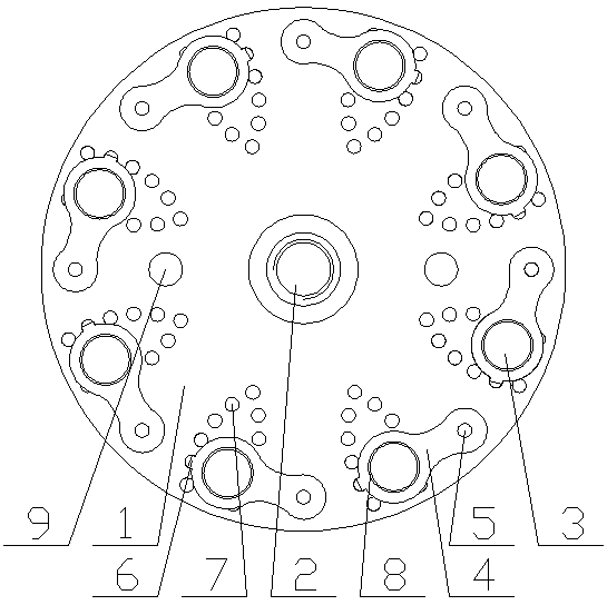
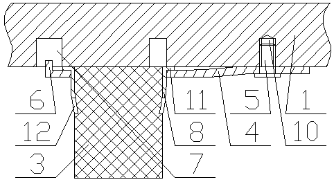
[0034] Combine figure 1 with figure 2 It can be seen that the present invention includes an ingot 1 with a through hole 2 for fixing the shaft at the center of the ingot 1, and 8 damping blocks 3 are evenly distributed on the edge of the bottom surface of the ingot 1, the damping blocks 3 is fixed to the ingot 1 by a spring sheet 4, the damping block 3 is fixed to one end of the spring sheet 4, the other end of the spring sheet 4 is rotatably connected to the ingot 1 through a pin 5, and the spring sheet 4 is located in the damping One end of the block 3 is provided with a hook 6 which is clamped in a positioning groove 7 provided on the bottom surface of the ingot 1, on the ingot 1, located in the circle surrounded by the through hole 2 and the damping block 3. There is also a pair of threaded through holes 9 therebetween, and the top surface of the spindle 1 is fixed with a positioning block matching the yarn reel through the threaded through holes 9; the distance between th...


PUM


Abstract

The invention discloses a damping wharve structure for spinning frames. The center of a wharve is provided with a through hole used to fix a shaft lever; the bottom edge of the wharve is evenly provided with a plurality of damping blocks; the damping blocks are fixed to the wharve through spring plates; the damping blocks are fixed to one ends of the spring plates, and the other ends of the springplates are rotationally connected to the wharve through pins; the end of each spring plate at the corresponding damping block is provided with a hook that hooks inside one positioning groove arrangedin the bottom of the wharve; the wharve is also provided with a pair of threaded through holes between the through hole and a circle made up of the damping blocks; the top of the wharve is fixedly provided with positioning blocks through the threaded through holes, wherein the positioning blocks cooperate to position the wharve; distances between the pins and the wharve are less than or equal tominimum distances between the pins and the damping blocks. It can be known from the above structure that the damping wharve structure herein ensures tension stability for a spinning frame that runs.

Description

Technical field [0001] The invention relates to the technical field of spinning frame spindles, in particular to a spinning frame spindle structure with a damping effect. Background technique [0002] Spinning machine, a spinning machine that drafts, twists, and winds semi-finished roving or sliver into a spinning bobbin in the spinning process. The sliver is drafted and twisted on the roving frame to make roving, and the combing machine combs the fibers. The sliver is combined into combed sliver, needle carding machine, needle row drafting improves the sliver structure, and the roving is further twisted and spun into spun yarn on the ring spinning frame. The spinning frame is the main spinning machine. The output and quality of spun yarn are a comprehensive reflection of the pros and cons of each process in the spinning process. [0003] The drafting of the spinning frame is the process of drawing the strands. The essence of drafting is to make the fibers move relative to each ot...

Claims


Application Information

Patent Timeline
Patent Type & Authority Patents(China)
IPC IPC(8): D01H13/10
CPCD01H13/104
Inventor 刘义涛
Owner 江苏华茂自动化设备有限公司
Why Eureka
Try Eureka