Swirl shaft flood discharging tunnel with volute chamber aerator

A technology of aeration sills and flood discharge tunnels, which is applied in marine engineering, construction, barrage/weir, etc., can solve the problems of increased project cost, complex aeration structure, and increased risk of cavitation and cavitation on the wall of shafts, so as to reduce construction costs. Difficulty, increase the air entrainment concentration, improve the effect of anti-cavitation cavitation performance

Active Publication Date: 2019-11-08
SICHUAN UNIV
View PDF6 Cites 6 Cited by
  • Summary
  • Abstract
  • Description
  • Claims
  • Application Information

AI Technical Summary

Problems solved by technology

[0004] However, due to the gradual increase in the height of the current shaft, the risk of cavitation and cavitation on the shaft wall is gradually increasing. Some shafts with high flow rates need to install separate aeration facilities at appropriate positions in the shaft to ensure the cavitation resistance of the shaft wall. , and the construction of a separate aeration facility greatly increases the project cost, and the existing aeration structures are relatively complex, which will undoubtedly increase the difficulty of constructing the shaft structure; The connection part of the cylindrical vortex chamber needs to be kept completely tangent, otherwise the wall surface will be uneven to form an artificial convex body and become a source of cavitation, which puts forward very high requirements for construction accuracy

Method used


Image

  • Swirl shaft flood discharging tunnel with volute chamber aerator
  • Swirl shaft flood discharging tunnel with volute chamber aerator
  • Swirl shaft flood discharging tunnel with volute chamber aerator

Examples


Embodiment 1

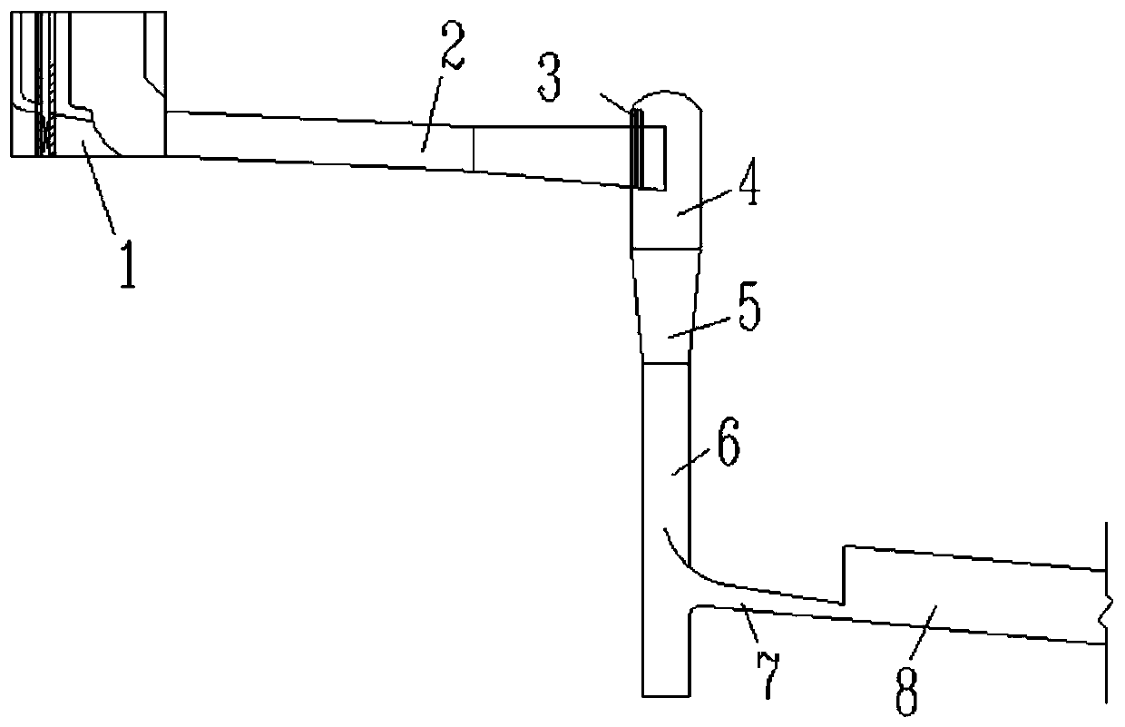
[0026] This embodiment provides a swirl shaft flood discharge tunnel with a vortex chamber aeration sill. The flood discharge tunnel is composed of a sluice chamber inlet 1, an upper flat section 2, a vortex chamber 4, a contraction section 5, a shaft straight section 6, and an outlet pressure slope. Section 7 and the subsequent lower horizontal drainage section 8, the vortex chamber is provided with a small shaft sill 3, the end of the side wall of the upper plane section is located in the vortex chamber, intersects with the wall surface of the vortex chamber, and the end is close to the vortex chamber. The wall surface of the chamber forms a vertical aeration ridge 7 attached to the wall surface of the vortex chamber, so that when the water flows through, an aeration cavity is formed between the aeration ridge and the wall surface of the vortex chamber to realize aeration.

[0027] During construction design, a vertical aeration sill is formed in the vortex chamber by moving ...

Embodiment 2

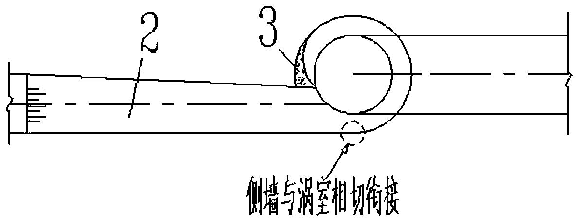
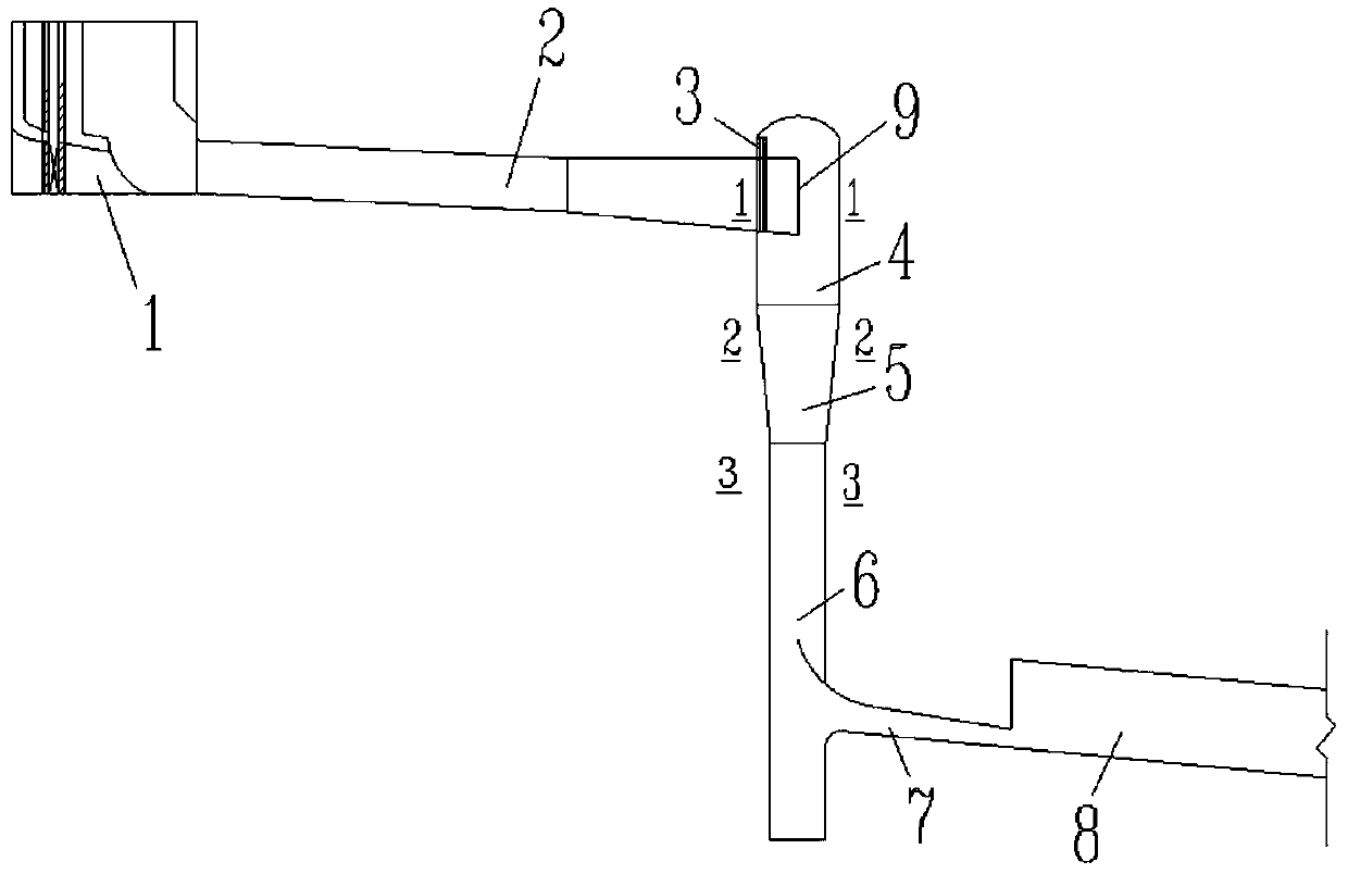
[0029] This embodiment provides a swirl shaft flood discharge tunnel with a vortex chamber aeration sill. The flood discharge tunnel is composed of a sluice chamber inlet 1, an upper flat section 2, a vortex chamber 4, a contraction section 5, a shaft straight section 6, and an outlet pressure slope. Section 7 and the subsequent lower horizontal drainage section 8, the vortex chamber is provided with a vertical well sill 3, the side wall of the upper plane section intersects with the arc wall of the vortex chamber, and the end of the side wall enters the vortex chamber, forming The vertical aeration sill 7 attached to the wall of the vortex chamber enables an aeration cavity to be formed between the aeration sill and the wall of the vortex chamber when water flows through, thereby realizing aeration.

[0030] During the construction design, a vertical aeration sill is formed in the vortex chamber by shifting the side wall tangentially connected to the vortex chamber to the vort...


PUM


Abstract

The invention provides a swirl shaft flood discharging tunnel with a volute chamber aerator. A side wall originally connected with a volute chamber shifts towards the center side of the volute chamberby a distance, and therefore the vertical aerator is formed in the volute chamber. When water flow passes through a step-down floor, an aerated cavity is formed, external air continuously carries outneeded gas supply on the water flow close to the wall side through the cavity, the aerated concentration of the water flow close to the wall is increased, and therefore the cavitation and cavitationerosion resistance of a whole shaft structure is greatly improved. Meanwhile, the aerated structure is far simpler than a conventional shaft aerator, and the engineering design difficulty and engineering cost can be greatly reduced. In addition, a fold line structure of the aerator replaces an original smoothly tangent structure, the engineering construction difficulty is greatly reduced, and thecavitation erosion and cavitation resistance of the connected position of the aerator and the shaft structure is improved.

Description

technical field [0001] The invention belongs to the field of flood discharge and energy dissipation in water conservancy and hydropower projects, and in particular relates to a novel swirl shaft flood discharge tunnel with vortex chamber aeration sills. Background technique [0002] The swirling shaft flood discharge tunnel has attracted more and more attention from the field of water conservancy and hydropower engineering because of its advantages such as low difficulty in construction, flexible layout, and outstanding energy dissipation effect. Especially as my country is currently in the stage of blowout development of hydropower construction, many high dams and large reservoirs with high water head, large flow, and deep canyons are under construction or are in the planning stage. Conventional drainage structures cannot well realize flood discharge. In the case of energy, the swirl shaft is a good choice as a newly developed flood discharge and energy dissipation building....

Claims


Application Information

Patent Timeline
Patent Type & Authority Applications(China)
IPC IPC(8): E02B8/06
CPCE02B8/06
Inventor 白瑞迪刘文
Owner SICHUAN UNIV
Why Eureka
Try Eureka