
Image identification technology-based non-contact displacement detecting device and method

A non-contact, displacement detection technology, applied in the direction of measuring devices, optical devices, instruments, etc., can solve the problems of increased work costs, leakage of power supply wires, low work efficiency, etc., with simple methods, accurate results, and easy use of equipment long life effect

Pending Publication Date: 2019-11-08
ELECTRIC POWER RESEARCH INSTITUTE OF STATE GRID QINGHAI ELECTRIC POWER COMPANY +1
View PDF0 Cites 5 Cited by
  • Summary
  • Abstract
  • Description
  • Claims
  • Application Information

AI Technical Summary

Problems solved by technology

The contact sensor needs to be in contact with the device under test to accurately measure data, but the field environment is more complicated, and the sensor will fail or be damaged in bad weather, resulting in low work efficiency and increased work costs
Furthermore, traditional conventional displacement detection devices often use an external power supply. When working in the field, it is very troublesome to connect the power supply. At the same time, the power supply wire leaks outside. Under the harsh conditions in the field, it is easy to damage and is not easy to carry.

Method used


Image

  • Image identification technology-based non-contact displacement detecting device and method
  • Image identification technology-based non-contact displacement detecting device and method
  • Image identification technology-based non-contact displacement detecting device and method

Examples


Embodiment 1

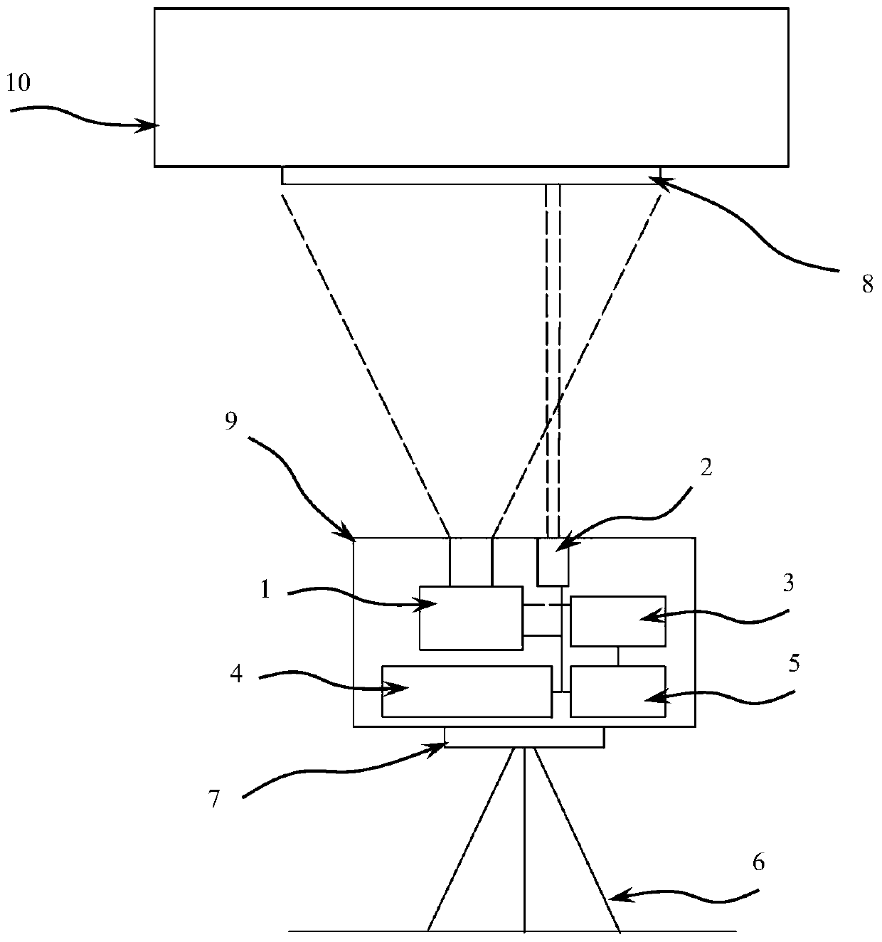
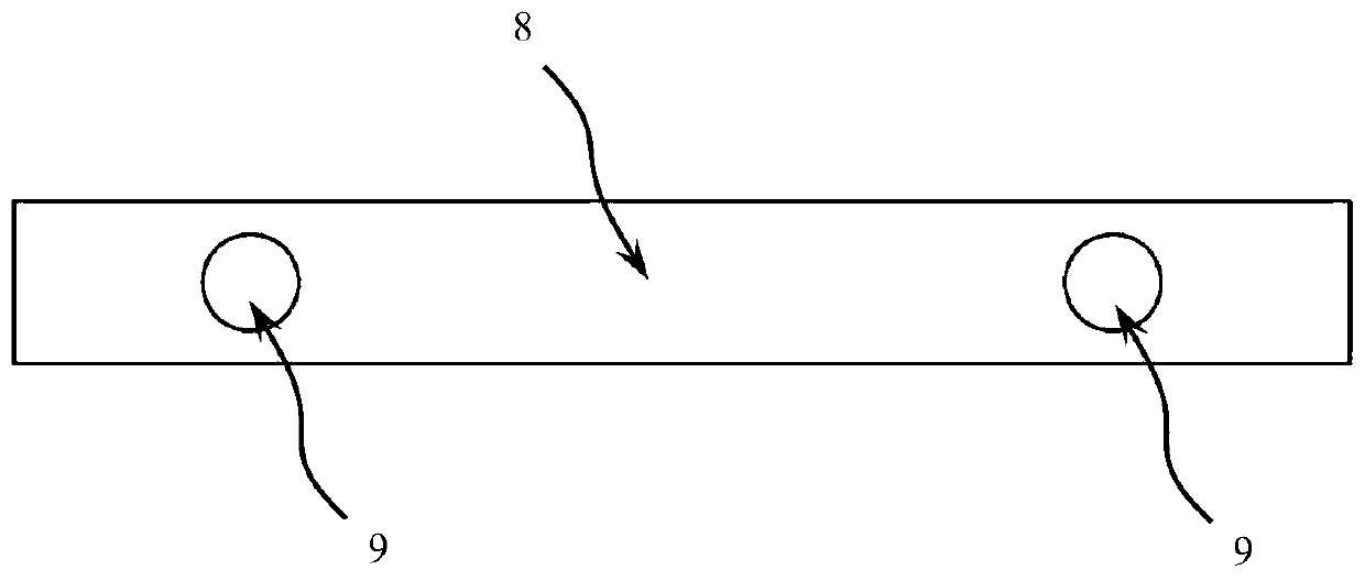
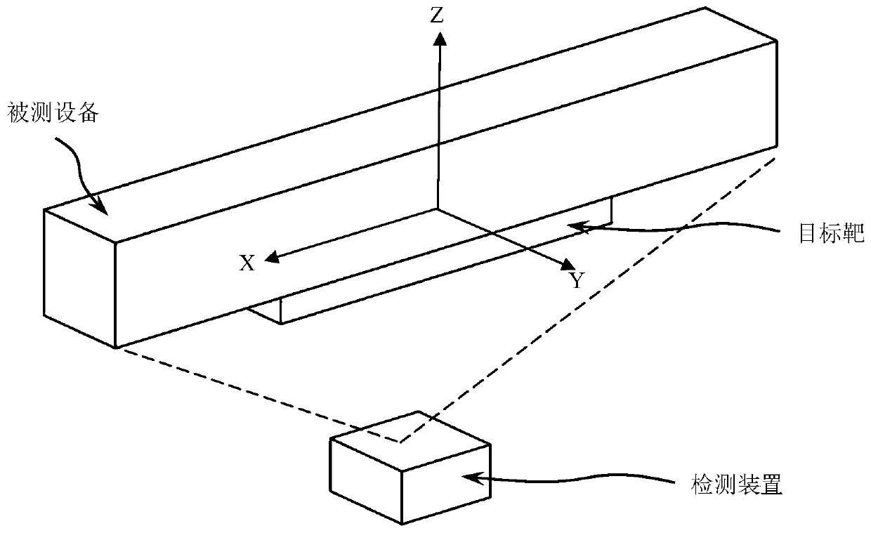
[0082] combine Figure 1~3 As shown, a non-contact displacement detection device based on image recognition technology includes an image acquisition module 1, a laser generating unit 2, a data storage and transmission module 3, a power supply and control module 5, and a target 8; the image acquisition module 1, The laser generation unit 2 and the data storage and transmission module 3 are respectively connected with the power supply and the control module 5; the image acquisition module 1 is connected with the data storage and transmission module 3; the distance between the image acquisition module 1 and the laser generation unit 2 is fixed; the target 8 is set on the detection equipment; two circles are set on one exposed surface of the target target 8 .

[0083] The image acquisition module 1 is a high-precision, high-definition camera.

Embodiment 2

[0085] combine Figure 1~3As shown, a non-contact displacement detection device based on image recognition technology includes an image acquisition module 1, a laser generating unit 2, a data storage and transmission module 3, a power supply and control module 5, and a target 8; the image acquisition module 1, The laser generation unit 2 and the data storage and transmission module 3 are respectively connected with the power supply and the control module 5; the image acquisition module 1 is connected with the data storage and transmission module 3; the distance between the image acquisition module 1 and the laser generation unit 2 is fixed; the target 8 is set on the detection equipment; two rectangles are set on one exposed surface of the target target 8 . The image acquisition module 1 is a high-precision, high-definition camera.

[0086] The device also includes an adjustable support 6, a base 7 and a casing 9; the image acquisition module 1, the laser generating unit 2, t...

Embodiment 3

[0088] combine Figure 1~3 As shown, a non-contact displacement detection device based on image recognition technology, the device includes an image acquisition module 1, a laser generating unit 2, a data storage and transmission module 3, a power supply and control module 5 and a target 8; Acquisition module 1, laser generating unit 2 and data storage and transmission module 3 are respectively connected with power supply and control module 5; image acquisition module 1 is connected with data storage and transmission module 3; distance between image acquisition module 1 and laser generation unit 2 fixed; the target target 8 is set on the detection device; two hexagons are set on one exposed surface of the target target 8 . The image acquisition module 1 is a high-precision, high-definition camera.

[0089] The device also includes an adjustable support 6, a base 7 and a casing 9; the image acquisition module 1, the laser generating unit 2, the data storage and transmission mo...


PUM


Abstract

The invention belongs to the field of equipment detection, and particularly relates to an image-identification technology-based non-contact displacement detecting device and a method for detecting displacement of a detected device through the device. The device comprises an image acquisition module (1), a laser generation unit (2), a data storage and transmission module (3), a power supply and control module (5) and an objective target (8); the image acquisition module (1), the laser generation unit (2) and the data storage and transmission module (3) are connected with the power supply and the control module (5) separately; the image acquisition module (1) is connected with the data storage and transmission module (3); the distance between the image acquisition module (1) and the laser generation unit (2) is fixed; the objective target (8) is arranged on the detecting device; at least one of the exposed surfaces of the objective target (8) is provided with at least two patterns with geometric centers. The device has the advantages that convenience is brought to carrying and installation; the application range is wide, the adaptability is high, and the service life is long; the measurement method is simple, and the result is accurate; deformation and displacement in three directions can be detected at the same time, and the efficiency is high.

Description

technical field [0001] The invention belongs to the field of equipment detection, and in particular relates to a non-contact displacement detection device based on image recognition technology and a method for detecting the displacement of a device under test using the device. Background technique [0002] Various field equipment (such as: GIS equipment, oil pipelines, etc.) are exposed to the field for a long time, and their failure frequency is relatively high. Most of the failure reasons are caused by thermal expansion and cold contraction of equipment. Due to the influence of the temperature difference between day and night, the equipment in the field will have a large displacement and deformation, which will cause a series of problems such as bending and cracking of the equipment. Before the problem is eliminated, the operation and maintenance personnel of the equipment will invest a lot of manpower and material resources to ensure the normal operation of the equipment,...

Claims


Application Information

Patent Timeline
Patent Type & Authority Applications(China)
IPC IPC(8): G01B11/02G01B11/16
CPCG01B11/02G01B11/16
Inventor 王志惠杨小库康钧王志敏刘高飞陈莲君何喜梅石径付宣蓉王生杰张烁曲全磊蒋玲李渊周尚虎黄中华韩兵于鑫龙陈文强王生富郑勇张海春郝卫新王鹏飞李生平
Owner ELECTRIC POWER RESEARCH INSTITUTE OF STATE GRID QINGHAI ELECTRIC POWER COMPANY
Learn More