Four-limb bone tumor positioned puncture device

A technology for tumor localization and extremity bones, which is applied in stereotaxic surgical instruments, medical science, surgery, etc., and can solve problems such as inconvenient limb puncture

Active Publication Date: 2019-11-12
高丽萍
View PDF6 Cites 4 Cited by
  • Summary
  • Abstract
  • Description
  • Claims
  • Application Information

AI Technical Summary

Problems solved by technology

But this puncture device is not convenient to puncture limbs

Method used


Image

  • Four-limb bone tumor positioned puncture device
  • Four-limb bone tumor positioned puncture device
  • Four-limb bone tumor positioned puncture device

Examples


specific Embodiment approach 1

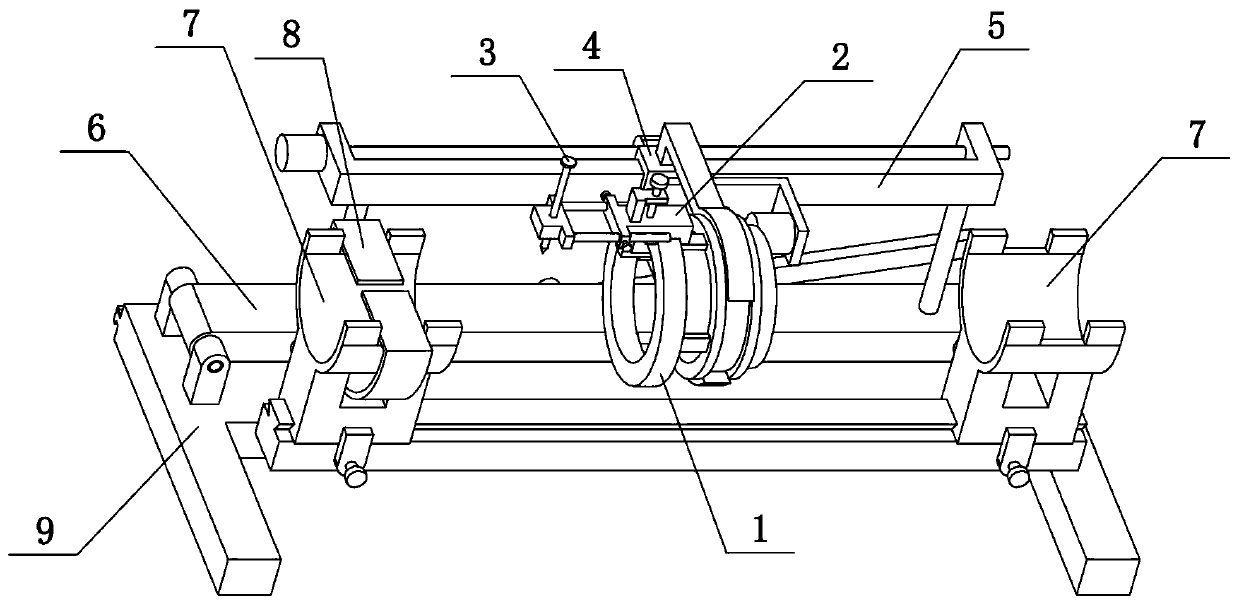
[0039] Combine below Figure 1-13 To illustrate this embodiment, the present invention relates to a puncture device, more specifically a puncture device for positioning bone tumors in extremities, including a ring 1, a circular swivel seat 2, a ring matching groove 201, an arc panel 202, and a vertical sliding column 204, top screw 205, threaded hole plate 206, puncture nail 3 and nail seat 301, the present invention can pass the limbs through the ring 1, and the puncture nail 3 can be fixed at any position on the ring 1, which is convenient for different limbs position for puncture.

[0040]The lower side of the said circumferential swivel seat 2 is provided with a ring matching groove 201, and the circumferential swivel seat 2 is buckled on the outer periphery of the ring 1 through the ring fitting groove 201, and the circumferential swivel seat 2 is slidably connected with a vertical sliding post 204, which is vertically slidable. The upper and lower ends of the column 204...

specific Embodiment approach 2

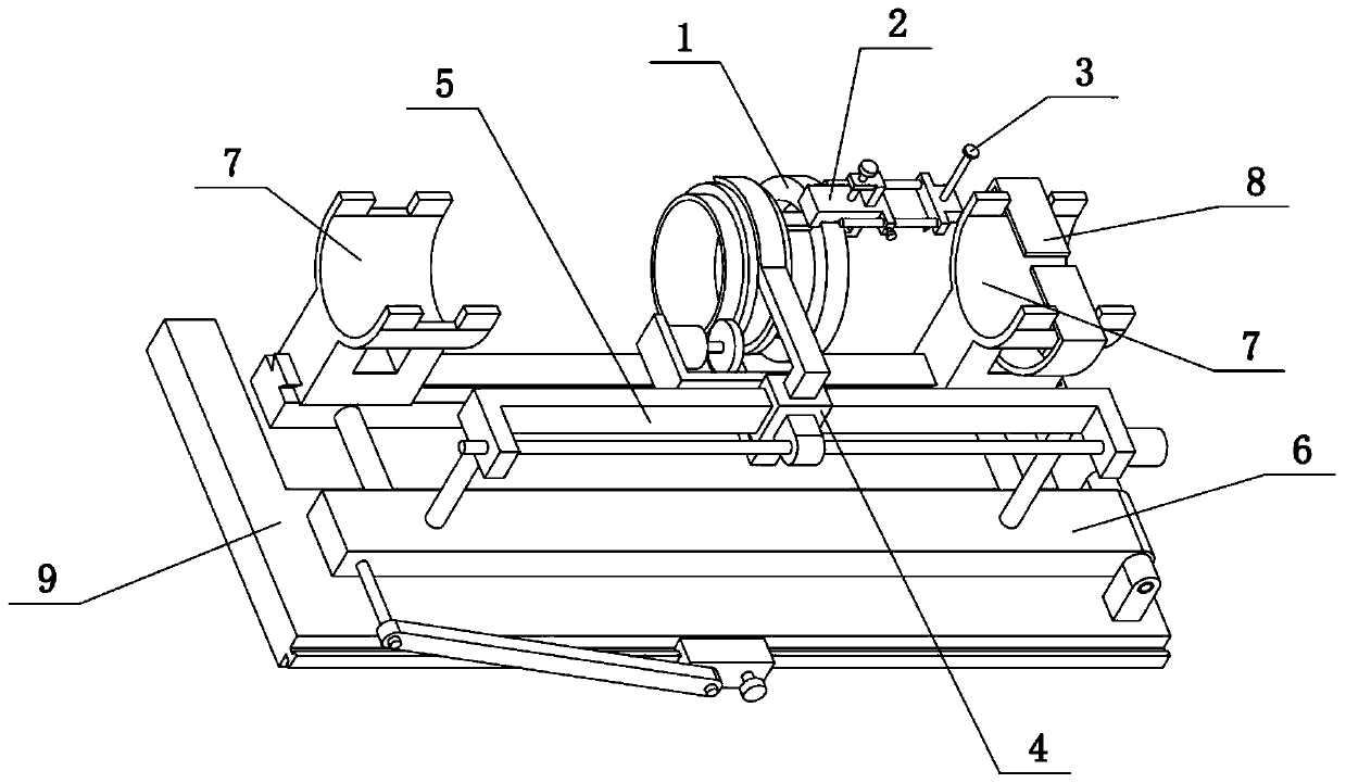
[0042] Combine below Figure 1-13 To illustrate this embodiment, the limb bone tumor localization and puncture device also includes fastening screws 1203 and round rods 302. Two round rods 302 are fixedly connected to one side of the nail seat 301, and the two round rods 302 are both slidably connected to the circumference of the circle. On the seat 2, two fastening screws I203 are threadedly connected on the circumferential rotary seat 2, and the two fastening screws I203 are supported on the two round rods 302 respectively. The two round rods 302 can slide on the circular swivel base 2 to adjust the left and right positions of the puncture nails 3. Multiple puncture nails 3 can be set on the ring 1 to puncture the bone tumor at different positions for many times. Turning the fastening screw 1203 can fix the positions of the two smooth rods 302, and then fix the position of the nail seat 301.

specific Embodiment approach 3

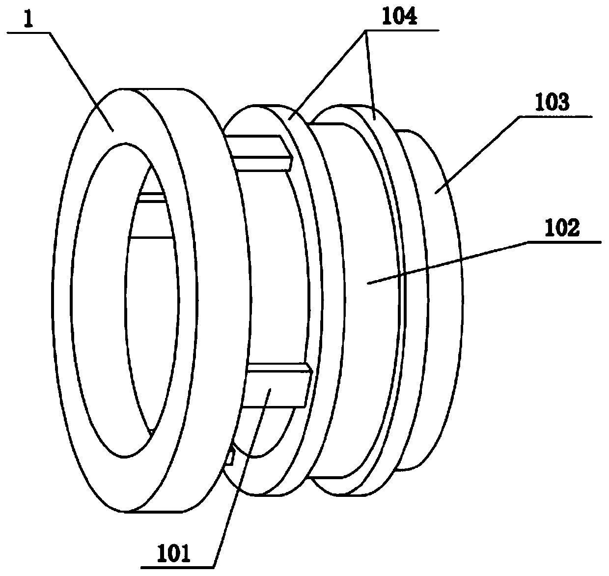
[0044] Combine below Figure 1-13 To illustrate this embodiment, the limb bone tumor positioning and puncture device also includes a connecting piece 101, a rotating cylinder 102, a ring edge 104, a sliding sleeve 4 and an arc-shaped rod 401, and the right side of the ring 1 is provided with a plurality of connecting pieces in a ring shape. 101, the right side of a plurality of connecting pieces 101 is fixedly connected with a rotating cylinder 102, the left and right ends of the rotating cylinder 102 are fixedly connected with ring ribs 104, the upper and lower ends of the sliding sleeve 4 are fixedly connected with an arc rod 401, the rotating cylinder 102 is rotatably connected between two arc-shaped rods 401 , and the two arc-shaped rods 401 are both located between the two ring edges 104 . The rotating drum 102 can rotate between the two arc-shaped rods 401. After the circumferential rotating base 2 and the ring 1 are fixed together, the position of the puncture nail 3 ca...


PUM


Abstract

The invention relates to a puncture device, in particular to a four-limb bone tumor positioned puncture device. The puncture device comprises a ring, a circumferential rotating seat, a ring matching groove, an arc plate, a vertical slide post, a top screw, a threaded perforated plate, puncture screws and a screw seat. Four limbs can penetrate through the ring and fixed in any position of the ring,so that different positions of four limbs can be punctured. The ring matching groove is formed in the lower side of the circumferential rotating seat, the circumferential rotating seat is buckled onthe periphery of the ring through the ring matching groove, the vertical slide post is glidingly connected onto the circumferential rotating seat, upper and lower ends of the vertical slide post are fixedly connected with the threaded perforated plate and the arc plate, the upper side surface of the arc plate is an arc surface, the arc surface of the arc plate is attached to the inner circumference of the ring, the threaded perforated plate is connected with the top screw through threads, the lower end of the top screw props against the upper side of the circumferential rotating seat, the screw seat is arranged on one side of the circumferential rotating seat, and the puncture screws are inserted in the screw seat.

Description

technical field [0001] The invention relates to a puncture device, in particular to a puncture device for positioning bone tumors in extremities. Background technique [0002] The application number is an orthopedic puncture biopsy device disclosed in CN201821093396.9. This utility model discloses an orthopedic puncture biopsy device, which is characterized in that it includes a cannula, a puncture needle, a spatula and clamping forceps; the cannula One end of the puncture needle is provided with a hand-held part, and the end surface of the other end is provided with evenly distributed serrations; one end of the puncture needle is provided with a connecting seat, and the other end is provided with a needle head, and the connecting seat can be connected to the hand-held part; The spoon can extend into the casing and stretch out from the other end of the casing. The end of the scraper is spoon-shaped, and the scraper is provided with a handle; The operating wire of the operat...

Claims


Application Information

Patent Timeline
IPC IPC(8): A61B90/14A61G13/12
CPCA61G13/1235A61G13/1245A61G13/124A61G13/125A61B90/14
Inventor 高丽萍蔡三许文婧石丽娜熊燕
Owner 高丽萍
Why Eureka
Try Eureka