Al technical title is built by PatSnap Al team. It summarizes the technical point description of the patent document.
A locator and fully automatic technology, applied in the field of medical devices, can solve problems such as difficult deployment in grass-roots hospitals, large radiation doses to patients, cumbersome operations, etc., and achieve good market prospects, simple structure, and good performance.
Inactive Publication Date: 2016-10-26
HARBIN JINYU SCI & TECH
View PDF13 Cites 7 Cited by
Summary
Abstract
Description
Claims
Application Information
AI Technical Summary
This helps you quickly interpret patents by identifying the three key elements:
Problems solved by technology
Method used
Benefits of technology
Problems solved by technology
[0002] At present, when performing CT positioning and puncture operations, medical personnel first stick a CT positioning scale on the body surface of the puncture target, and then determine the puncture point and puncture angle through CT scanning according to the relationship between the metal scale point on the scan map and the puncture target. , and then select the puncture point on the human body to insert the needle, mainly relying on the experience and technical level of the operator to puncture towards the imaginary target. Repeated CT scans are required to confirm the position of the puncture needle. The operation is cumbersome and the radiation dose to the patient is large.
[0003] At present, the Pinpoint system consisting of laser positioning, reconstructed three-dimensional image stereotaxic positioning and manipulator is applied to CT interventional therapy. It has more advantages and is a great progress in CT interventional therapy, but the equipment is expensive and it is difficult to carry out in primary hospitals
Method used
Image
Click on the blue label to locate the original text in one second.
Reading with bidirectional positioning of images and text.
Examples
Embodiment Construction
[0021] The present invention will be further described below with reference to the accompanying drawings and examples, and the embodiments of the present invention include but not limited to the following examples.
[0022] Embodiment: In order to achieve the above object, the technical scheme adopted in the present invention is as follows:
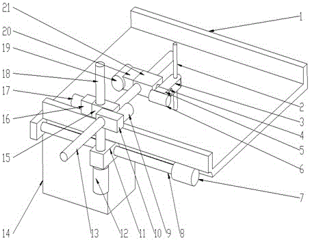
[0023] Such as figure 1 As shown, the present invention provides a fully automatic CT puncture positioner device, including a bed body 1, a guide needle 2, a bracket A3, a rotating shaft 4, a transmission unit A5, a stepping motor A6, a stepping motor B7, a lead screw A8, a stepper Incoming motor C9, transmission unit B10, bracket B11, stepping motor D12, screw B13, logic control unit 14, bracket C15, transmission unit C16, stepping motor E17, screw C18, stepping motor F19, transmission unit D20 and Bracket D21, stepping motor B7 is installed on the bed body 1, the two ends of the lead screw A8 are respectively installed on the bed body ...
PUM
Abstract
The invention discloses an automatic CT puncture locator device. The device includes a bed body, a guide needle, a bracket A, a rotating shaft, a driving unit A, a stepping motor A, a stepping motor B, a screw rod A, a stepping motor C, a driving unit B, a bracket B, a stepper motor D, a screw rod B, a logic control unit, a bracket C, a driving unit C, a stepping motor E, a screw rod C, a stepping motor F, a driving unit D, and a bracket D, the stepping motor is installed on the bed body, two ends of the screw rod A are respectively installed on the bed body and the stepping motor B, the screw rod C is vertically arranged on the screw rod A in a staggered manner through the bracket B, and the screw rod B is horizontally arranged on the bracket C in a crossed manner through the screw rod C, the driving unit B is mounted on the bracket C, the rotating shaft is vertically mounted on the screw rod B through the bracket D, the guide needle is vertically mounted on the rotating shaft through the bracket A, and the logic control unit is mounted on the bed body.
Description
technical field [0001] The invention belongs to the field of medical equipment, in particular to a fully automatic CT puncture positioner device. Background technique [0002] At present, when performing CT positioning and puncture operations, medical personnel first affix a CT positioning scale on the body surface of the puncture target, and through CT scanning, determine the puncture point and puncture angle according to the relationship between the metal scale point on the scan map and the puncture target. , and then select the puncture point on the human body to insert the needle, mainly relying on the experience and technical level of the operator to puncture the imaginary target. Repeated CT scans are required to confirm the position of the puncture needle. The operation is cumbersome and the radiation dose to the patient is large. [0003] At present, the Pinpoint system consisting of laser positioning, reconstructed three-dimensional image stereotaxic positioning and...
Claims
Application Information
Patent Timeline
Application Date:The date an application was filed.
Publication Date:The date a patent or application was officially published.
First Publication Date:The earliest publication date of a patent with the same application number.
Issue Date:Publication date of the patent grant document.
PCT Entry Date:The Entry date of PCT National Phase.
Estimated Expiry Date:The statutory expiry date of a patent right according to the Patent Law, and it is the longest term of protection that the patent right can achieve without the termination of the patent right due to other reasons(Term extension factor has been taken into account ).
Invalid Date:Actual expiry date is based on effective date or publication date of legal transaction data of invalid patent.