Hook-type front fork and handlebar fast disassembly bicycle structure
A technology for bicycles and front fork risers, which is applied to bicycle accessories, transportation and packaging, steering mechanisms, etc., can solve the problems of inconvenient assembly, increased labor and material costs, etc.
- Summary
- Abstract
- Description
- Claims
- Application Information
AI Technical Summary
Problems solved by technology
Method used
Image
Examples
Embodiment 1
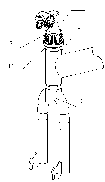
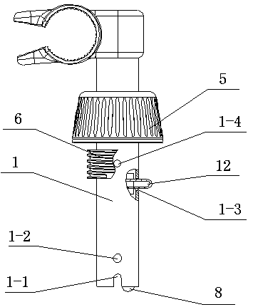
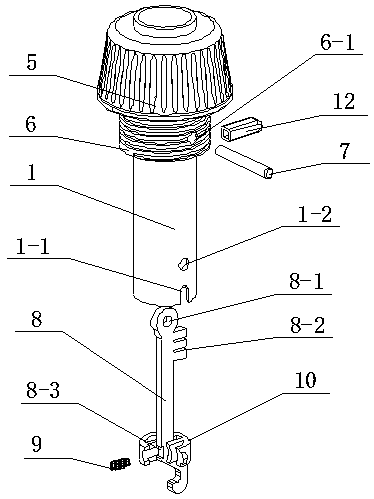
[0030] see Figure 1-6 , a bicycle structure with a hook-type front fork and a stem that can be quickly disassembled, including a stem 1, a frame head tube and a headset 2 at the lower part of the stem 1, and a connection between the stem 1 and the frame head tube and headset 2 A spacer 11 is provided between them, a front fork 3 is provided at the lower end of the stem 1, a stud 6 is arranged at the upper part of the stem 1, and the stud 6 is threadedly connected with a nut 5, and the upper part of the front fork 3 is provided with a front fork standpipe pin 3-1, the front fork standpipe pin shaft 3-1 is clipped to the card slot 1-1 at the bottom of the stem 1 to ensure the synchronous rotation of the stem 1 and the front fork 3, and the upper part of the stem 1 is provided with a handlebar The pin hole 1-4, the handlebar pin hole 1-4 runs through the connecting pin 7, the middle part of the stud 6 is provided with a stud hole 6-1, the stud hole 6-1 is connected with the hand...
Embodiment 2
[0032] see Figure 7-8 , the other content of this embodiment is the same as that of Embodiment 1, the difference is that: the lower part of the nut 5 is provided with a relief groove 5-1, and the inner diameter of the relief groove 5-1 is greater than the length of the button 12. At this time, the button 12 and Not in contact with the relief groove 5-1 at the bottom of the nut 5, the right side of the guide groove 10-3 is provided with a limiting boss 8-5, and the lower part of the hook 8 is provided with a guide slope 8-4. During use, under the action of the spring 9 and the stopper boss 8-5 of the hook 8, the hook 8 is in the state of hooking the pin shaft 3-1 of the front fork standpipe, and when the hook 8 moves downward, the guide slope 8-4 and the When the front fork standpipe pin 3-1 contacts, the hook 8 rotates, and finally under the action of the spring 9, the lower end of the hook 8 is engaged with the front fork standpipe pin 3-1, which is different from the touch ...
Embodiment 3
[0034] see Figure 9-10, the other content of this embodiment is the same as that of Embodiment 1, the difference is that: the left side of the upper part of the hook 8 is provided with a button slot 8-2, the button slot 8-2 is engaged with the button 12, and the nut 5 A retaining ring 13 is provided between the spacer 11, and the middle part of the retaining ring 13 is provided with a fixing hole 13-1, and the fixing hole 13-1 is connected to the threaded hole 5-2 provided at the lower end of the nut 5 by bolts. This working method is free locking. On the basis of the second embodiment, the position of the button 12 on the hook 8 is moved to the left side, and the through hole 1-3 of the stem 1 is also moved to the left side accordingly. When the nut 5 When moving downwards, the button 12 is placed in the step-off groove 5-1, at this time, under the action of the spring 9, the hook 8 is engaged with the pin shaft 3-1 of the front fork riser, at this time, the stem 1 and the f...
PUM
 Abstract
Description
Claims
Application Information
 - R&D
- Intellectual Property
- Life Sciences
- Materials
- Tech Scout
- Unparalleled Data Quality
- Higher Quality Content
- 60% Fewer Hallucinations
Browse by: Latest US Patents, China's latest patents, Technical Efficacy Thesaurus, Application Domain, Technology Topic, Popular Technical Reports.
© 2025 PatSnap. All rights reserved.Legal|Privacy policy|Modern Slavery Act Transparency Statement|Sitemap|About US| Contact US: help@patsnap.com


