
Manufacturing device and manufacturing method of composite electrolytic plate

An electrolytic plate and equipment technology, which is applied in the field of composite electrolytic plate production equipment, can solve problems such as poor alkali cleaning effect, easy peeling off of the coating, poor activation state of the thin steel plate surface, etc., to achieve the effect of ensuring flatness and benefiting electroplating

Inactive Publication Date: 2019-11-12
江苏诺优空气净化设备有限公司
View PDF5 Cites 0 Cited by
  • Summary
  • Abstract
  • Description
  • Claims
  • Application Information

AI Technical Summary

Problems solved by technology

[0005] The present invention can solve the problem of poor alkaline cleaning effect of the existing steel plate during alkaline cleaning, incomplete cleaning of grease on the outside of the thin steel plate, resulting in poor electroplating effect of the thin steel plate, easy peeling of the coating on the outer side of the thin steel plate, and inability to clean the thin steel plate The rust on the outside is cleaned, resulting in the uneven surface of the thin steel plate after electroplating, and when the thin steel plate is pickled, the pickling time cannot be adjusted according to the thickness of the thin steel plate and the oxidation degree of the thin steel plate surface, so that the thin steel plate The activation state of the surface is poor, leading to problems such as poor plating effect on thin steel plates

Method used


Image

  • Manufacturing device and manufacturing method of composite electrolytic plate
  • Manufacturing device and manufacturing method of composite electrolytic plate
  • Manufacturing device and manufacturing method of composite electrolytic plate

Examples


Embodiment Construction

[0033] The embodiments of the present invention will be described in detail below with reference to the accompanying drawings, but the present invention can be implemented in many different ways defined and covered by the claims.

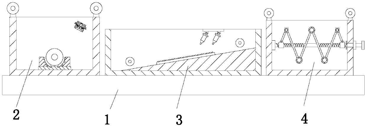
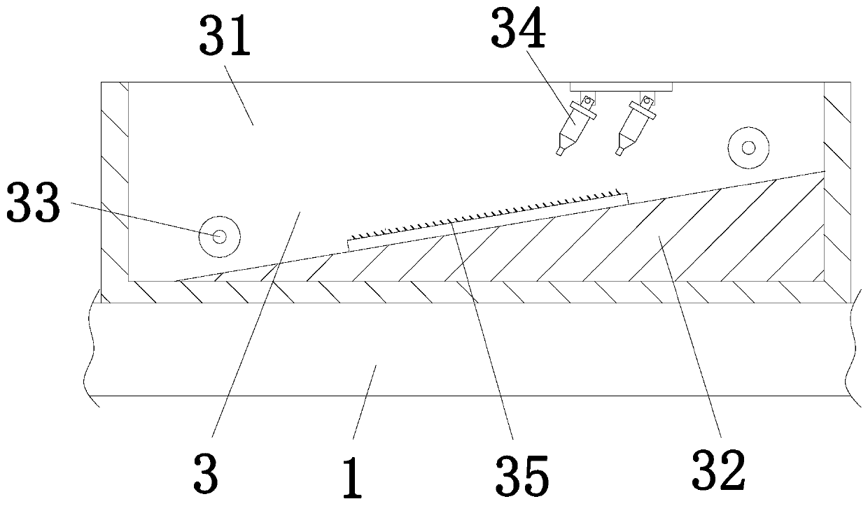
[0034] Such as Figure 1 to Figure 5 As shown, a composite electrolytic plate production equipment includes a base plate 1, an alkali cleaning device 2, a water washing device 3 and an acid pickling device 4. The base plate 1 is equipped with an alkali cleaning device 2 on the left side of the upper end, and the upper end of the base plate 1 is installed in the middle. There is a washing device 3, and a pickling device 4 is installed on the right side of the upper end of the bottom plate 1.

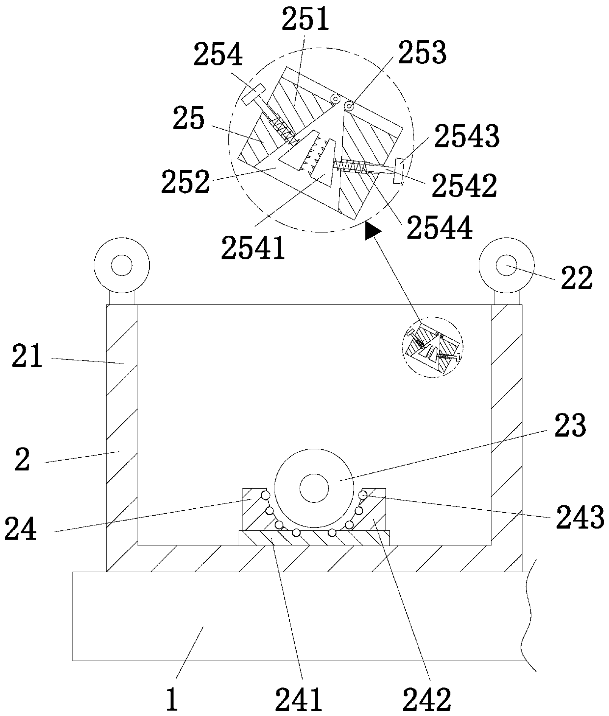
[0035] Described alkaline cleaning device 2 comprises alkaline cleaning tank 21, No. 1 guide roller 22, cleaning roller 23, cleaning frame 24 and scraping mechanism 25, and described alkaline cleaning tank 21 is installed on the left side of base plate 1 upper ...


PUM


Abstract

The invention relates to a manufacturing device and a manufacturing method of a composite electrolytic plate. The manufacturing device and manufacturing method of the composite electrolytic plate comprises a bottom plate, an alkali washing device, a water washing device and an acid washing device. An alkali washing device is installed on the left side of the upper end of the bottom plate, a waterwashing device is installed in the middle of the upper end of the bottom plate, and an acid washing device is installed on the right side of the upper end of the bottom plate. According to the manufacturing device and the manufacturing method, the problems that the existing alkali washing effect of the steel plate is poor, and the oil cleaning outside the steel plate is incomplete, which result inthat the plating effect of the steel plate is poor, and the plating layer outside the steel plate is easy to fall off; meanwhile, rust on the outside of the steel plate cannot be peeled off, resulting in uneven surface of the steel sheet after electroplating; and when the thin steel plate is subjected to acid washing, the pickling time cannot be adjusted according to thickness of the thin steel plate and oxidation degree of the thin steel plate surface, so that the activation state of the thin steel plate surface is poor, and the electroplating effect of the thin steel plate is poor, and thelike are solved.

Description

technical field [0001] The invention relates to the field of electrolytic plate production, in particular to a production equipment and a production method of a composite electrolytic plate. Background technique [0002] The electrolytic plate is rolled by the cold tandem rolling unit and then annealed by the CAPL unit, and then enters the electro-galvanizing unit. After the surface is cleaned and electroplated, it can be treated with phosphating, passivation, oiling, fingerprint resistance, alloying, etc. according to different purposes. The resulting product, electrolytic plate, also known as electro-galvanized plate, uses electrolysis to form a uniform, dense, and well-bonded metal or alloy deposition layer on the surface of the thin steel plate. The electroplating layer is widely used to protect steel parts, especially to prevent atmospheric corrosion. , and used for decoration. [0003] The existing electrolytic plate production equipment usually has the following defe...

Claims


Application Information

Patent Timeline
Patent Type & Authority Applications(China)
IPC IPC(8): C23G3/00
CPCC23G3/00
Inventor 袁有华潘昆明
Owner 江苏诺优空气净化设备有限公司
Learn More