Connecting rod transmission self-locking mechanism

A technology of connecting rod transmission and connecting rod, which is applied to building locks, building structures, building fastening devices, etc. The production and installation are convenient, the structure design is simple and reasonable, and the production cost is low.

Pending Publication Date: 2019-11-12
宁波生久科技有限公司
View PDF10 Cites 0 Cited by
  • Summary
  • Abstract
  • Description
  • Claims
  • Application Information

AI Technical Summary

Problems solved by technology

[0003] In order to overcome the above-mentioned shortcomings, the purpose of the present invention is to provide a link transmission self-locking mechanism in the field, so that it can solve the problem that the existing similar products are difficult to apply long link displacement, installation and production are more inconvenient, and the linkage self-locking effect is not good. technical problem

Method used


Image

  • Connecting rod transmission self-locking mechanism
  • Connecting rod transmission self-locking mechanism
  • Connecting rod transmission self-locking mechanism

Examples


Embodiment Construction

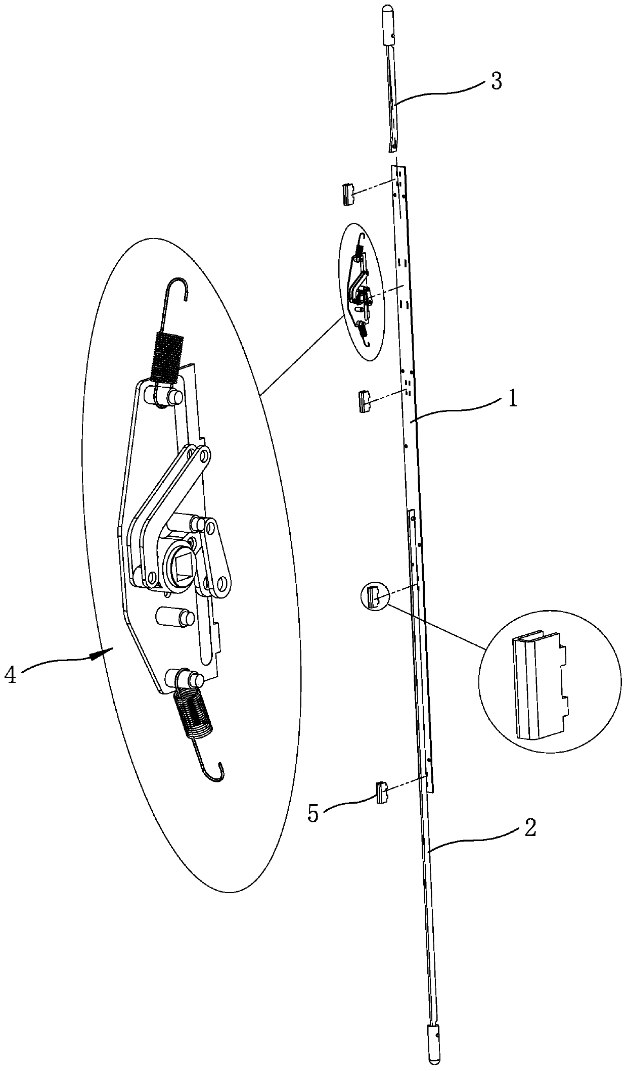
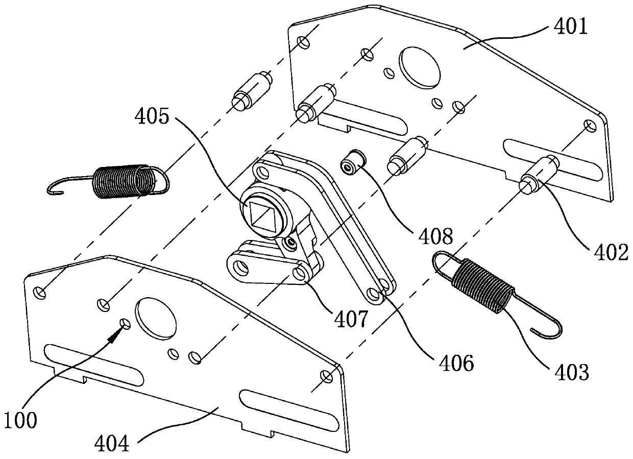
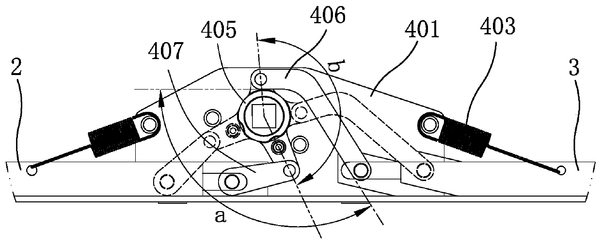
[0020] Now in conjunction with the accompanying drawings, the structure of the present invention will be further described. Such as Figure 1-Figure 4 As shown, the two ends of the connecting rod bottom plate 1 of this mechanism are respectively connected to one end of the lower connecting rod 2 and one end of the upper connecting rod 3 through the connecting rod pressing plate 5, and the upper connecting rod and the lower connecting rod protruding from the connecting rod pressing plate are respectively pulled One end of the spring 403 is connected with the transmission assembly 4, the center of the rotating shaft 405 of the transmission assembly is provided with a square lock hole, the square lock hole of the rotating shaft is at least aligned with the side plate lock hole of one side plate, and the first side plate and the second side plate pass through The fixed limit pin 402 is connected and fixed. The specific structure of the above-mentioned connecting rod pressing plat...


PUM


Abstract

The invention relates to a connecting rod transmission self-locking mechanism designed for solving the technical problems that existing similar products are difficultly applied to long connecting roddisplacement, mounting and production are inconvenient, and the linkage self-locking effect is poor. The two ends of a connecting rod bottom plate of the connecting rod transmission self-locking mechanism are connected with one end of a lower connecting rod and one end of an upper connecting rod through connecting rod pressing plates correspondingly, one ends of the upper connecting rod and lowerconnecting rod with the junctions stretching out of the connecting rod pressing plates are connected with a transmission assembly through tension springs correspondingly, and a square lock hole is formed in the center of a rotating shaft of the transmission assembly. According to the key points of the connecting rod transmission self-locking mechanism, lower connecting rod connecting pieces are arranged at a connecting lever on one side of the rotating shaft of the transmission assembly, one ends of the lower connecting rod connecting pieces are connected with the connecting lever of the rotating shaft, and the other ends of the lower connecting rod connecting pieces are connected with a tail end rivet of the lower connecting rod; and an edge lug is arranged on the other side, symmetricalto the connecting lever, of the rotating shaft, upper connecting rod connecting pieces are arranged at the edge lug of the rotating shaft, one ends of the upper connecting rod connecting pieces are connected with the edge lug of the rotating shaft, the other ends of the upper connecting rod connecting pieces are connected with a tail end rivet of the upper connecting rod, and fixing limiting pinsare fixed to the other ends of the tension springs of the transmission assembly.

Description

technical field [0001] The invention relates to a link lock, which is a link transmission self-locking mechanism. Background technique [0002] The link lock is a kind of metal cabinet door used in telecommunications, electric power, automation control manufacturing and other industries. It is used to lock the metal plate cabinet frame, or a cover lock similar to the door frame or box frame. It includes parallel to the door edge, and A formed link, such as a flat bar, that stands substantially upright on the door or frame; also includes at least one retainer mounted on the door frame or door for connecting the link when the door is locked in the closed position; and a link attached to the door panel. lever operating device. The link transmission self-locking mechanism in this kind of link lock, such as the application number 201420252462.8 disclosed in the Chinese patent literature, the date of authorization announcement is 2014.12.10, and the name of the utility model is "...

Claims


Application Information

Patent Timeline
Patent Type & Authority Applications(China)
IPC IPC(8): E05C9/04E05B65/02E05B65/52
CPCE05C9/043E05B65/025E05B65/5238
Inventor 姚春良毛建华
Owner 宁波生久科技有限公司
Why Eureka
Try Eureka