Displacement amplification ultrasonic linear motor and working method thereof

A technology of displacement amplification and linear motors, which is applied to generators/motors, piezoelectric effect/electrostrictive or magnetostrictive motors, electrical components, etc., can solve problems such as low efficiency, large loss, and short life, and achieve Reduced manufacturing cost, low work loss, and long service life

Inactive Publication Date: 2013-09-18
刘勤
View PDF4 Cites 0 Cited by
  • Summary
  • Abstract
  • Description
  • Claims
  • Application Information

AI Technical Summary

Problems solved by technology

[0010]However, due to the structure and force transmission mode of the existing ultrasonic linear motor, there are defects such as small thrust, low efficiency, large loss, short life, and slow speed. needs improvement

Method used


Image

  • Displacement amplification ultrasonic linear motor and working method thereof
  • Displacement amplification ultrasonic linear motor and working method thereof
  • Displacement amplification ultrasonic linear motor and working method thereof

Examples


Embodiment 1

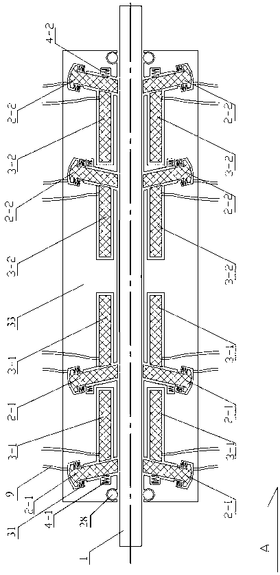
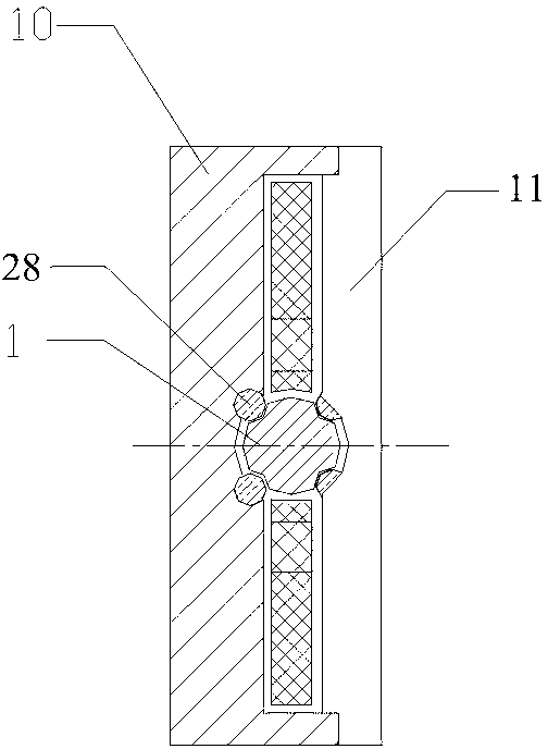
[0047] Such as figure 1 and 2 As shown, the present invention is mainly composed of a motor stator with a central hole and a motor mover 1 penetrating through the central hole. The motor stator is mainly composed of a stator housing and a radial concave The stator housing is mainly composed of the stator housing A11 and the stator housing B12 buckled together, and the radial groove and the axial groove are arranged radially and vertically along the central hole respectively. Axial setting; one end of the radial groove communicates with the central hole, and the left or right side of the radial groove is provided with a spring groove communicating with it; the axial groove is located on the right side of the radial groove Or the left side, and communicate with the radial groove; the radial piezoelectric strip is arranged in the radial groove, the axial piezoelectric strip is arranged in the axial groove, and the spring one is arranged in the spring groove.

[0048] In the pr...

Embodiment 2

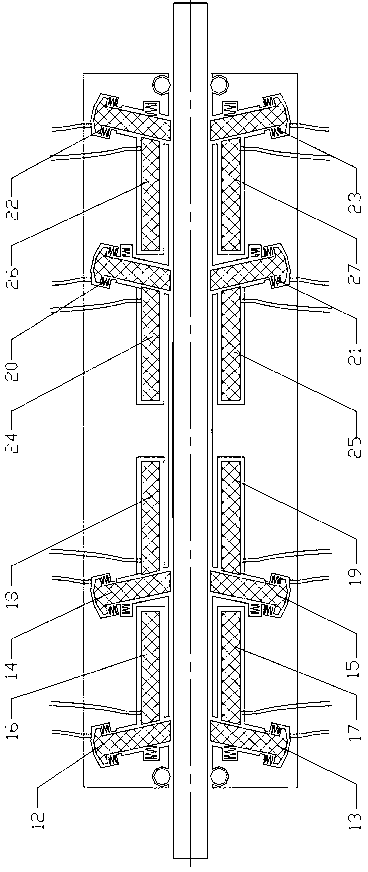
[0063] Due to the existing piezoelectric materials or components used to manufacture piezoelectric strips, the displacement (stretch) of each power-on and power-off cycle can only be a few thousandths of the device size at most, but can be a few percent The device is still under development, and the technology is very difficult; and the cost of the piezoelectric strip is high. If the displacement (stretching) of each power-on and power-off cycle is to be increased, the usage of the piezoelectric strip will inevitably increase, which will increase the manufacturing cost of the motor. In order to overcome the above shortcomings, increase the displacement stroke of each action cycle, thereby increasing the speed of the motor, making up for the speed of this type of motor and reducing the manufacturing cost, such as Figure 4 As shown, in the present invention, the end of the radial groove far away from the central hole is also connected with a radial force arm cavity and a radial ...


PUM


Abstract

The invention discloses a displacement amplification ultrasonic linear motor which mainly comprises a motor stator with a centre hole and a motor rotor penetrating in the center hole, wherein the motor stator mainly comprises a stator shell as well as a radial groove and an axial groove which are arranged on the stator shell; the radial groove and the axial groove are radially arranged and axially arranged along the center hole respectively; one end of the radial groove is communicated with the center hole; the left side or right side of the radial groove is provided with a spring groove communicated with the radial groove; the axial groove is positioned on the right side or left side of the radial groove and communicated with the radial groove; a radial piezoelectric strip is arranged in the radial groove; an axial piezoelectric strip is arranged in the axial groove; and a spring is arranged in the spring groove. The invention also discloses a working method of the displacement amplification ultrasonic linear motor. The displacement amplification ultrasonic linear motor disclosed by the invention has the advantages of large thrust, high efficiency, low loss, high speed and long service life.

Description

technical field [0001] The invention relates to a displacement amplifying ultrasonic linear motor suitable for positioning and driving in various occasions such as precision measurement, metering, office automation equipment, industrial appliances, household appliances, robots, automobiles, and aerospace equipment, and a working method thereof. Background technique [0002] Ultrasonic linear motor is a motor that uses piezoelectric material crystals to deform under the action of an external electric field as a driving force to generate linear motion. This ultrasonic linear motor has the following characteristics: [0003] 1. It does not need to be like other types of linear motors. It converts electrical energy into mechanical energy for linear motion based on the principle that the current-carrying conductor receives electromotive force in a magnetic field. [0004] 2. There are no coils and iron cores in the stator and mover parts, and the structure is simple, small in si...

Claims


Application Information

Patent Timeline
Patent Type & Authority Patents(China)
IPC IPC(8): H02N2/02H02N2/04H02N2/06
Inventor 刘勤
Owner 刘勤
Why Eureka
Try Eureka