Electric luggage compartment door

A technology for luggage compartments and hatches, which is applied to doors, door/window accessories, hydraulic/pneumatic locks, etc. It can solve problems such as deformation of the sealing strip of the hatch body, affecting the normal use of the hatch, and deformation of the hatch body. Small space, good switching performance, and the effect of improving switching performance

Pending Publication Date: 2019-11-12
法美瑞控股有限公司
View PDF0 Cites 4 Cited by
  • Summary
  • Abstract
  • Description
  • Claims
  • Application Information

AI Technical Summary

Problems solved by technology

The control box is inside the luggage compartment, taking up space
Secondly, after the pneumatic luggage compartment door of the bus is closed, the connection between the lock core and the lock buckle of the door lock is in the first-level lock position, and then the cabin door body needs to be further tightened so that the lock core and lock buckle of the door lock enter the second-level lock position , that is, the secondar

Method used


Image

  • Electric luggage compartment door
  • Electric luggage compartment door
  • Electric luggage compartment door

Examples


Embodiment 1

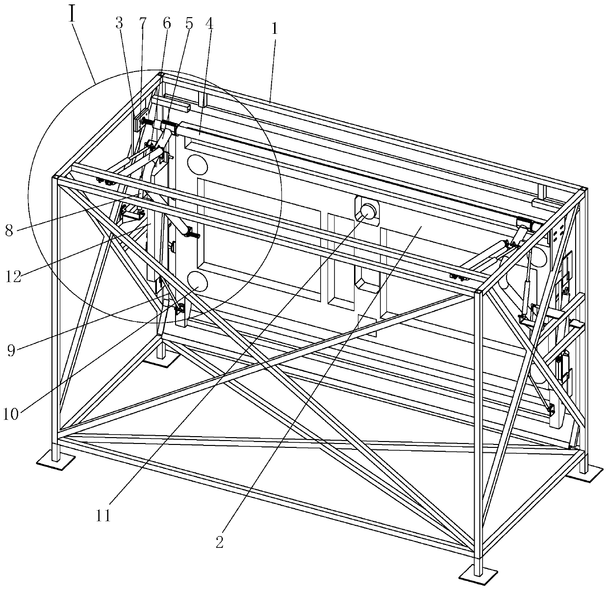
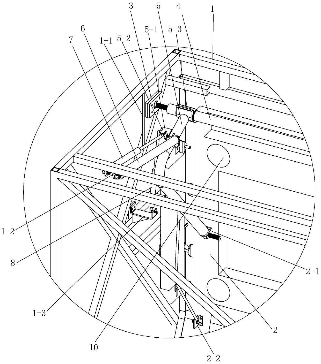
[0021] See Figure 1 to Figure 7 , Embodiment 1 has a frame 1, a hatch body 2, a swing arm 5, a hatch body electric strut 6, a first gas spring 7, a second gas spring 8, an unlocking mechanism 11 and a tensioning mechanism 12.

[0022] The hatch body 2 is at the front side of the frame. Frame 1 left and right sides top near hatch body respectively is fixed with frame first bracket 1-1, and frame first bracket 1-1 is fixed with bearing block 3, and two bearing blocks 3 each support a rotating shaft 4 through the rolling bearing in it, Both ends of the rotating shaft 4 are respectively fixed on a curved swing arm 5 through a connecting clip 5-3, and the end of the swing arm 5 is dynamically connected to the first bracket 2-1 of the door body in the middle of the hatch body 2, A top support 5-1 and a side support 5-2 are fixed on one side near the rotating shaft 4 on each swing arm 5 .

[0023] The left and right sides of the top of the frame 1 are respectively fixed with a fra...


PUM


Abstract

The invention provides an electric luggage compartment door. The electric luggage compartment door is provided with a frame and a compartment door body; bearing seats are fixed to the parts, close tothe compartment door body, of the upper parts of the left side and the right side of the frame; the two bearing seats support a rotating shaft; curved swinging arms are fixed to the two ends of the rotating shaft; the ends of the swinging arms are movably connected with the middle part of the back of the compartment door body; each of the left side and the right side of the top of the frame is movably connected with a compartment door body electric strut and a first gas spring; the compartment door body electric struts and first gas springs have the identical inclination degrees and are parallel; the end of the compartment door body electric strut and the end of the first gas spring which are on each side are movably connected with the top surface of the upper part of the corresponding swinging arm; the middle parts of the left side and the right side of the frame are movably connected with second gas springs; the ends of the second gas springs are movably connected with the side surfaces of the upper parts of the corresponding swinging arms; at least one door lock is arranged on each of the left side and the right side of the compartment door body; and door lock tensioning mechanisms are arranged on the left side and the right side of the frame. The electric luggage compartment door is simple in structure and convenient to mount, the space usage rate of a luggage compartment is increased substantially, it is guaranteed that the compartment door body is normally opened and closed, and the electric luggage compartment door has the good opening-closing performance.

Description

technical field [0001] The present invention relates to electric luggage compartment doors. Background technique [0002] The pneumatic luggage compartment door of a traditional bus needs a cylinder to drive the shaft, and a gas spring as an auxiliary, so as to drive the swing arm to move up and close the luggage compartment door. The control box is inside the luggage compartment and takes up space. Secondly, after the pneumatic luggage compartment door of the bus is closed, the connection between the lock core and the lock buckle of the door lock is in the first-level lock position, and then the cabin door body needs to be further tightened so that the lock core and lock buckle of the door lock enter the second-level lock position , that is, the secondary lock is installed, so as to ensure that the door lock is always in a locked state. Since the tensioning mechanism uses a cylinder, the cylinder still tightly pulls the hatch body inward through the control shaft, and keep...

Claims


Application Information

Patent Timeline
IPC IPC(8): E05F15/60E05B81/10E05B81/66E05B83/22E05F3/02B60J5/04
CPCB60J5/047B60J5/0497E05B81/10E05B81/66E05B83/22E05F3/02E05Y2900/54E05F15/60
Inventor 顾惠芬
Owner 法美瑞控股有限公司
Why Eureka
Try Eureka