Sieve pipe self-locking switch controller

A self-locking switch and manipulator technology, which is used in the production of fluids, wellbore/well components, and earth-moving drilling, etc., and can solve the high positioning requirements (the convex shoots must be inserted into the matching grooves to complete the opening. Closing action, large (specially running tools, and the wellhead is required to cooperate with pressure, only one sliding sleeve is controlled, etc., to achieve the effect of low downhole positioning requirements, reduced construction complexity, and improved construction safety.

Pending Publication Date: 2017-11-24
中石化石油工程技术服务有限公司 +2
View PDF10 Cites 6 Cited by
  • Summary
  • Abstract
  • Description
  • Claims
  • Application Information

AI Technical Summary

Problems solved by technology

The advantage of this patent is that it can effectively control the sliding sleeve at the designated position, but the disadvantages are also obvious, such as: a large amount of construction work for manipulation (tools are specially inserted, and the wellhead is required to cooperate with pressure); high positioning requirements (the convex shoots must be stuck just right) The opening and closing action can only be completed by entering the matching groove); it is required to only operate one sliding sleeve at a time, and the construction efficiency is low (in order to prevent misoperation, the size of the convex bamboo shoot can only match the groove of a designated sliding sleeve)
[0005] The applicant has previously applied for "sand control screen with self-locking switch" (utility model patent application number: 201720464297.6, invention patent application number 201710294013.8), but lacks more matching special tools

Method used


Image

  • Sieve pipe self-locking switch controller
  • Sieve pipe self-locking switch controller
  • Sieve pipe self-locking switch controller

Examples


Embodiment Construction

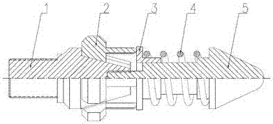
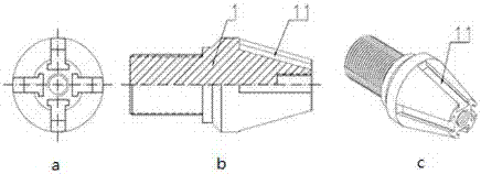
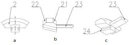
[0027] see figure 1 , a self-locking switch controller for screen tubes, including a tapered slide rail joint 1, a movable shift block 2, a spring pressing cap 3, a return spring 4, and a front guide head 5. Among them: both ends of the tapered slide rail joint 1 are threaded, and four dovetail grooves 11 are processed on the conical body, which are evenly distributed around the axis. The internal thread of the tapered slide rail joint 1 is fastened with the thread of the front leader 5, The front seeker 5 is covered with a spring pressure cap 3, and the spring pressure cap 3 and the front seeker 5 are in a sliding fit, and a return spring 4 is installed between the two. The movable shifting block 2 is a circular structure, and the bottom plane is processed. There is a T-shaped slide rail 24, and the T-shaped slide rail 24 is installed in the dovetail groove 11 of the tapered slide rail joint 1 and is in a sliding fit. Contact, the front part of the front guide head 5 is coni...


PUM


Abstract

The invention relates to a sieve pipe self-locking switch controller. The sieve pipe self-locking switch controller is mainly composed of a conical sliding rail connector, a movable stirring block, a spring pressing cap, a reset spring and a front guiding head. Two to six dovetail grooves evenly distributed in the circumferential direction of the axis are machined in a conical structure body of the conical sliding rail connector. The movable stirring block is of a round flaw structure, and T-shaped sliding rails are machined on the bottom face, arranged in the dovetail grooves of the conical sliding rail connector and are in sliding fit. A rod head is machined at the front end of the movable stirring block, the top end of the rod head makes contact with one end of the spring pressing cap, and the spring pressing cap is arranged on a shaft outer sleeve of the front guiding head and is in sliding fit. The reset spring is arranged between the spring pressing cap and the front guiding head shoulder part. The end of the front guiding head is a conical body. The sieve pipe self-locking switch controller is used in cooperation with a sand control sieve pipe with a self-locking switch, one or more sand control sieve pipes at the assigned position under a well can be controlled according to the actual needs and can be made to put into production or quit production, and accordingly the purposes of flow adjusting, water controlling and production system optimizing are achieved.

Description

technical field [0001] The invention relates to the field of downhole tools for oil well fracturing and oil production, in particular to a screen pipe self-locking switch manipulator capable of changing the functional state of a sand control sand filter pipe. Background technique [0002] The downhole sleeve switch is widely used in fracturing and oil production, and the fluid channel connecting the inside and outside of the working string is artificially opened and closed according to actual needs. The methods of controlling the switch action of the downhole sliding sleeve usually include electric control, hydraulic control, ball throwing (or throwing darts) and running into the sliding sleeve control tool. The above control methods have their own characteristics: [0003] The electronic control method is usually used in oil production, that is, the downhole cable connected to the ground drives the downhole motor to control the sliding sleeve (or special piston). The electr...

Claims


Application Information

Patent Timeline
Patent Type & Authority Applications(China)
IPC IPC(8): E21B43/08E21B34/14
CPCE21B34/14E21B43/086
Inventor 陈阳王绍先杨海波万绪新邵茹饶鸿飞马丁冯德杰张建国齐志刚李国锋李伟赵传伟
Owner 中石化石油工程技术服务有限公司
Why Eureka
Try Eureka