Continuous wall milling machine

A milling machine and milling technology, which is applied to sheet pile walls, earth movers/excavators, construction, etc., can solve the problems of wall strength influence, complicated maintenance, and low construction efficiency, so as to improve construction safety performance, Simple and convenient maintenance and high working stability

Inactive Publication Date: 2011-08-17
上海工程机械厂有限公司
View PDF5 Cites 23 Cited by
  • Summary
  • Abstract
  • Description
  • Claims
  • Application Information

AI Technical Summary

Problems solved by technology

However, this technology has the following problems: 1) Since the underground diaphragm wall is formed by overlapping unit columns, non-overlapping parts are likely to appear between the columns. When the adjacent overlapping columns are dislocated, the strength of the wall is affected, resulting in water leakage from the wall.
2) Since the column-type underground continuous wall is formed by overlapping, its cross-section is in the shape of candied haws strings with different widths. The width of the wall at the waist valley is the smallest and the strength is the weakest, which is prone to water leakage.
3) Since the column-type underground diaphragm wall is completed through the repeated steps of drilling, mixing, lifting, moving and lapping of each construction unit, the construction process is complicated and the construction progress is slow; especially for ultra-deep diaphragm walls Construction requires repeated addition of drill pipes, which greatly increases the work intensity of construction personnel and low construction efficiency
4) In order to improve the operation efficiency of the underground diaphragm wall and avoid the method of repeatedly lengthening the drill pipe, and adopt the construction method of drilling to the required depth at one time, a pile frame with a larger column height must be used, so the operation stability is poor, and piles are prone to occur. safety accident
However, this technology has the following problems: 1) Since the drive sprocket of the excavation mixing chain of the underground continuous excavator is installed on the outer circumference of the planetary reducer, the prime mover transmits power to the planetary reducer, and the power is transmitted to the planetary reducer through the planetary reducer. The driving sprocket meets the construction requirements of driving low-speed and high-torque. Because a large amount of heat is generated during the deceleration process from the high-speed rotating prime mover to the low-speed rotating driving sprocket, the temperature rise of the planetary reducer is accelerated, and the service life of the planetary reducer is reduced. Moreover, the maintenance is complicated, which greatly affects the construction efficiency of the underground diaphragm wall; 2) Since the spout of the curing agent is located at the lower end of the guide column, the sprayed curing agent is only mixed and stirred by the stirring rod on the chain in one direction, resulting in the failure of the diaphragm wall. The uneven distribution of curing agent content in the depth direction directly causes uneven internal quality of the cured wall, which affects the strength and water-proof and anti-seepage performance of the wall; 3) Since there is no deviation correction control system, the vertical accuracy of the wall cannot wait until Effective correction, so that the construction accuracy of the wall is affected

Method used


Image

  • Continuous wall milling machine
  • Continuous wall milling machine
  • Continuous wall milling machine

Examples


Embodiment Construction

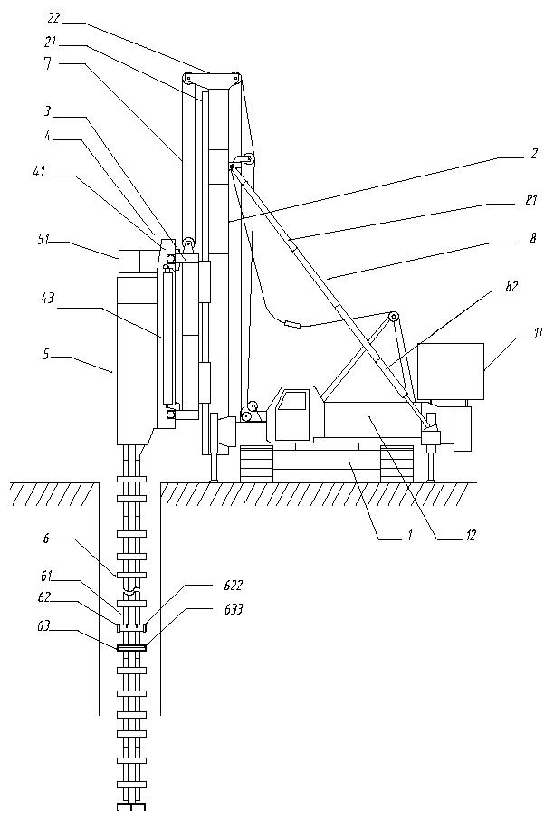
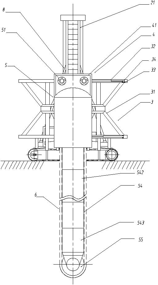
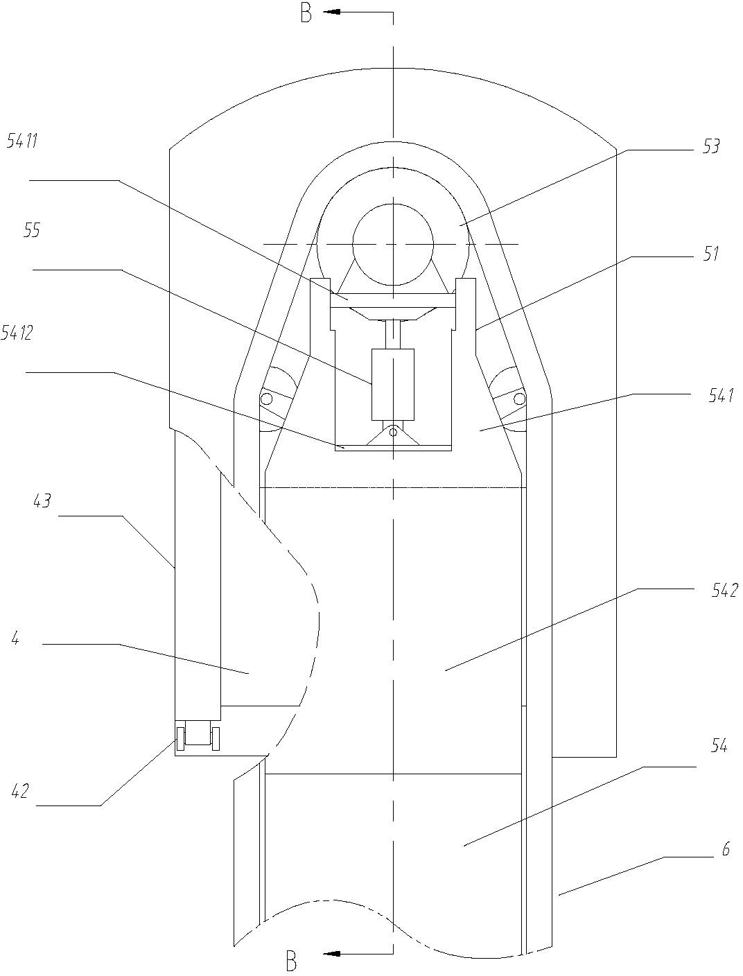
[0043] Such as figure 1 , figure 2 , image 3 , Figure 4 , Figure 5 , Figure 6 and Figure 7 As shown, a continuous wall milling machine includes: a host chassis 1, including a power source 11 and a hoist unit 12; a column 2, including a guide rail 21 and a top pulley frame 22; a door frame 3, including a frame body 31, and a horizontally moving oil cylinder 32. Transverse rail 33 and guide seat 34; guide frame 4, including frame body 41 with upper and lower rails, guide slider 42 and vertical jacking cylinder 43; milling box 5, including drive head 51 containing motor and planetary reducer , gearbox 52, driving sprocket 53, milling frame 54, tensioning oil cylinder 55, driven sprocket 56 and grouting pipe 57; milling frame 54 adopts box-type structure, including upper section 541, connecting member 542 and lower section 543 in turn Milling and stirring chain 6, comprising chain 61, some groups of milling cutter bodies 62 and some groups of stirring bodies 63 fixedly...


PUM


Abstract

The invention discloses a continuous wall milling machine, which comprises a host machine base plate, an upright post, a gantry frame, a guide frame, a milling box, a milling and stirring chain, a steel wire rope, an inclined strut and a correcting mechanism, wherein a milling frame adopts a box structure and can be extended to a set length; the milling and stirring chain comprises a chain, and multiple groups of crossed milling cutter bodies and multiple groups of stirring bodies which are fixedly arranged on the chain at certain intervals; after the chain is arranged on a driving chain wheel and a driven chain wheel, a chain transmission mechanism is formed; a transmission case is positioned on the upper part of the milling box; a driving head is fixedly arranged at an installation position above the transmission case; the driving chain wheel is arranged on an output shaft at the lower end of the transmission case; the output shaft is arranged on a supporting platform; one end of a tension oil cylinder is hinged with the lower part of the supporting platform, and the other end of the tension oil cylinder is connected with a lower rod piece; the correcting mechanism is used for obliquely correcting the front, back, left and right of the milling frame; multiple groups of grout pipes are arranged inside the milling frame along the length direction of the milling frame; and the end parts of the grout pipes are provided with spray heads. The continuous wall milling machine is suitable for underground facilities of large buildings, deep foundation excavation and cut-off wall construction of water conservancy dams.

Description

Technical field [0001] The invention relates to a continuous wall milling machine for drilling formations and constructing underground continuous walls of equal thickness in underground deep foundation engineering. Background technique [0002] At present, in the construction of underground facilities of large buildings, deep foundation excavation and anti-seepage walls of water conservancy dams, two technologies of multi-axis diaphragm wall drilling machine and underground continuous excavator are generally used for the construction of underground diaphragm wall. [0003] Multi-axis diaphragm wall drilling machine is used to construct column-type underground diaphragm wall, which is the widely used SMW construction method at present. Multi-axis diaphragm wall drilling machine is used to continuously drill, mix and lift, and mix soil and cement slurry in situ. Each construction unit is overlapped and drilled and excavated repeatedly to build an underground retaining and wate...

Claims


Application Information

Patent Timeline
Patent Type & Authority Applications(China)
IPC IPC(8): E02D5/18E02F5/14E02F5/06
Inventor 张慧颖陈文澜毛雪峰吴闫松张鹏
Owner 上海工程机械厂有限公司
Why Eureka
Try Eureka