
Mechanical sealing device with adjustable local film thickness between sealing end faces

A mechanical sealing device and sealing end technology, applied in mechanical equipment, engine sealing, engine components, etc., can solve the problems of difficulty in regulating the leakage rate and fluid film stiffness, and achieve sealing operation stability and service life improvement, and liquid film stiffness. The effect of lifting, leak rate regulation

Pending Publication Date: 2019-11-12
ZHEJIANG UNIV OF TECH
View PDF0 Cites 4 Cited by
  • Summary
  • Abstract
  • Description
  • Claims
  • Application Information

AI Technical Summary

Problems solved by technology

[0005] Aiming at the problem that the leakage rate and fluid film stiffness of the existing mechanical seal device are difficult to control, the present invention provides an adjustable mechanical seal that adjusts the leakage rate and fluid film stiffness by adjusting the deformation of the sealing end face and then adjusting the local film thickness between the end faces. device

Method used


Image

  • Mechanical sealing device with adjustable local film thickness between sealing end faces
  • Mechanical sealing device with adjustable local film thickness between sealing end faces
  • Mechanical sealing device with adjustable local film thickness between sealing end faces

Examples


Embodiment Construction

[0022] The technical scheme of the present invention is described in detail below in conjunction with accompanying drawing:

[0023] refer to figure 1 , Figure 2 and image 3 :

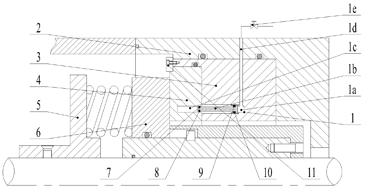
[0024] Such as figure 1 As shown, the local film thickness adjustable mechanical seal device between the sealing end faces includes a positioning ring 11, a moving ring 6, a moving ring seat 5, a static ring 4, a static ring seat 3, and a sealing end cover 2; the positioning ring 11 connects the static ring 4 Press on the static ring seat 3 to prevent the axial displacement of the static ring relative to the static ring seat; Rotate, a push spring is installed between the moving ring 6 and the moving ring seat 5; the static ring 4 is installed on the static ring seat 3, and the static ring seat 3 is installed on the sealing end cover 2; the static ring 4 faces the moving ring 6 One side of the static ring 4 is the end face, and the side of the static ring 4 facing away from the moving ring 6 is th...


PUM


Abstract

The invention provides a mechanical sealing device with the adjustable local film thickness between sealing end faces. The mechanical sealing device comprises a positioning ring, a movable ring, a movable ring seat, a fixed ring, a fixed ring seat and a sealing end cover. The fixed ring is compacted on the fixed ring seat through the positioning ring, the end face of the movable ring and the end face of the fixed ring axially cooperate, the movable ring is mounted on the movable ring seat and rotates along with a shaft, and a pushing spring is arranged between the movable ring and the movablering seat. The fixed ring is mounted on the fixed ring seat, and the fixed ring seat is mounted on the sealing end cover. An oil storage cavity is formed in the fixed ring, the oil storage cavity is ablind hole opened to the back face of the fixed ring, and the top end of the oil storage cavity is close to the end face of the fixed ring. A piston cavity is formed in the fixed ring seat, the piston cavity is a blind hole opened to the attached face of the fixed ring seat and the fixed ring, and the piston cavity and the oil storage cavity are butted to form a uniform cavity parallel to the axial direction. A double-head piston is arranged in the uniform cavity, one end of the double-head piston is located in the oil storage cavity, the other end of the double-head piston is located in thepiston cavity, the double-head piston moves in the axial direction of the uniform cavity in order to change the pressure in the oil storage cavity, and the piston cavity communicates with a pressure regulating valve through an air inflow passageway penetrating through the fixed ring seat and the sealing end cover in order to adjust the pressure in the piston cavity.

Description

technical field [0001] The invention relates to a shaft-end mechanical seal device, and is particularly suitable for mechanical seal applications requiring on-line adjustment of fluid film thickness and fluid film rigidity on the sealing end surface. Background technique [0002] Mechanical seals play a vital role in critical turbomachinery such as reactor coolant main pumps. The key to long life and high reliability of mechanical seals is continuous full-film lubrication, neither excessive leakage nor lack of lubrication between end faces in pursuit of too low leakage rate. When the leakage rate is too high or there is a lack of lubrication between the end faces, it will lead to changes in temperature and pressure in the sealing device, and the reliability of the seal will decrease, or even fail. When the seal fails, the seal can only be repaired by shutting down the reactor coolant pump, and the economic loss caused by shutting down the reactor coolant pump is huge. [0...

Claims


Application Information

Patent Timeline
Patent Type & Authority Applications(China)
IPC IPC(8): F16J15/34
CPCF16J15/3432F16J15/3452
Inventor 彭旭东金杰孟祥铠赵文静
Owner ZHEJIANG UNIV OF TECH
Learn More