A continuous heating water heater

A continuous heating and water heater technology, applied in water heaters, fluid heaters, lighting and heating equipment, etc., can solve the problems of slow hot water supply and unsatisfactory continuous use by users

Active Publication Date: 2021-05-11
JIANGXI MOLISI TECH CO LTD
View PDF7 Cites 0 Cited by
  • Summary
  • Abstract
  • Description
  • Claims
  • Application Information

AI Technical Summary

Problems solved by technology

[0004] The purpose of the present invention is to solve the problem that the hot water supply in the prior art is slow and cannot meet the continuous use of users, and proposes a continuous heating water heater

Method used


Image

  • A continuous heating water heater
  • A continuous heating water heater
  • A continuous heating water heater

Examples


Embodiment 1

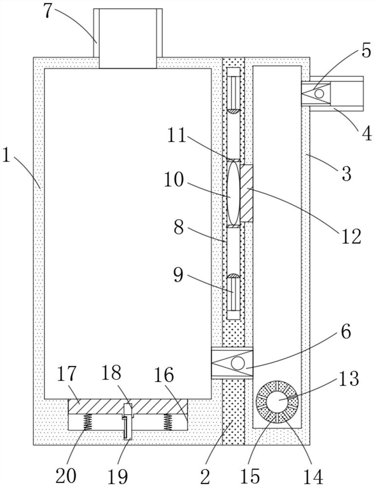
[0018] refer to figure 1 , a continuous heating water heater, comprising a hot water tank 1, an induction tank 2 and a heating tank 3, the two sides of the induction tank 2 are respectively welded to the hot water tank 1 and the heating tank 3, and the upper end of the heating tank 3 is connected through the side wall There is a water inlet pipe 4, the inner wall of the water inlet pipe 4 is glued with a water inlet valve 5, the inner wall of the lower end of the heating box 3 is penetrated and connected with a water supply valve 6, and the water supply valve 6 runs through the side walls of the induction box 2 and the hot water tank 1 to connect the heating box 3 with the hot water tank. The water tank 1 is connected, the upper end of the hot water tank 1 is connected with an outlet pipe 7, the bottom of the heating box 3 is welded with an electric heating rod 13, and the inside of the induction box 2 is provided with an induction chamber 8, and the inner walls of the upper an...

Embodiment 2

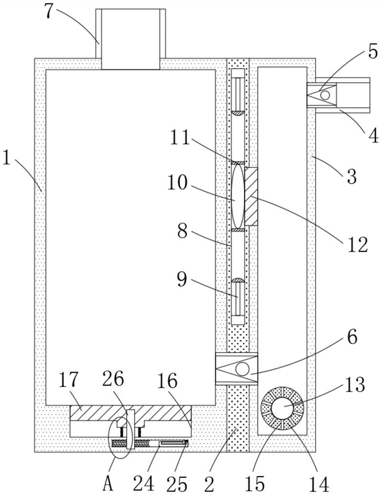
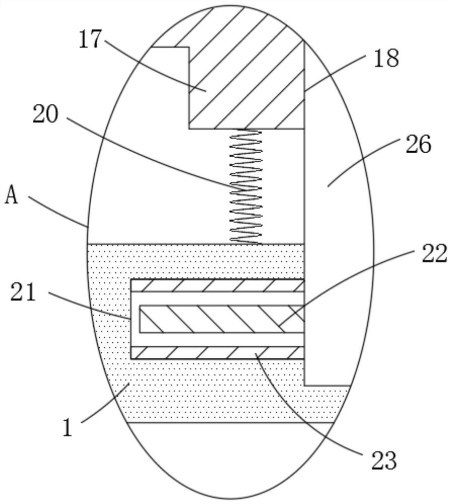
[0025] refer to Figure 2-3The difference between this embodiment and Embodiment 1 lies in the difference of the linkage device. The linkage device includes a linkage plate 17 and an indirect rheostat 24. The inner bottom of the hot water tank 1 is provided with a linkage groove 16, and the upper opening of the linkage groove 16 is glued with a layer of waterproof The film isolates the inner wall of the linkage groove 16 from the hot water inside the hot water tank 1 to ensure the existence of water pressure at both ends of the linkage plate 17. The inner wall of the linkage groove 16 is slidingly connected with the linkage plate 17, and the bottom of the linkage plate 17 is provided with linkage holes 18. The inner wall of the interlocking hole 18 is threadedly connected with the rotating shaft 26, and the thread lead angle of the threaded connection is greater than the equivalent friction angle of the screw pair, so that the rotation of the interlocking hole 18 and the rotati...


PUM


Abstract

The invention discloses a continuous heating water heater, which comprises a hot water tank, an induction tank and a heating tank. There is a water inlet pipe, the inner wall of the water inlet pipe is glued with a water inlet valve, and the inner wall of the lower end of the heating tank is connected with a water supply valve, and the water supply valve runs through the side walls of the induction tank and the hot water tank to connect the heating tank with the hot water tank , the upper end of the hot water tank is connected with a water outlet pipe, and the bottom of the heating tank is welded with an electric heating rod. The advantage is that in the present invention, the heat in the heating box is transferred to the induction bag through the heat sensitive sheet, so that the induction bag is heated and expanded, and then the contact sheet is attached to the contact block to realize the on-off of the water supply valve and the water inlet valve Only when the water flow in the heating tank is heated to the set value can it enter the hot water tank through the pressure of the subsequent injected cold water, so that the water heat in the hot water tank can be replenished in time.

Description

technical field [0001] The invention relates to the technical field of water heaters, in particular to a continuous heating water heater. Background technique [0002] A water heater refers to a device that raises the temperature of cold water into hot water within a certain period of time through various physical principles. According to different principles, it can be divided into electric water heaters, gas water heaters, solar water heaters, magnetic energy water heaters, air energy water heaters, heating water heaters, etc. [0003] At present, during the use of electric water heaters, when the hot water in the water tank is conveying hot water to the outside, cold water is continuously replenished into the water tank and heated at the same time to meet the use of hot water. However, this cold water directly The method of replenishing the water tank will cause the hot water to be used at a faster rate, and more cold water will be injected, resulting in a rapid drop in ...

Claims


Application Information

Patent Timeline
Patent Type & Authority Patents(China)
IPC IPC(8): F24H1/18F24H9/18F24H9/20
CPCF24H1/185F24H9/1818F24H9/2021
Inventor 陈凡
Owner JIANGXI MOLISI TECH CO LTD
Why Eureka
Try Eureka