Gas tightness detection device

A technology of air tightness detection and equipment, which is applied in the field of machinery, can solve the problems of long clamping and positioning time, single structure, and reduced detection efficiency, and achieve the effects of ensuring stability, high integration, and compact overall structure

Active Publication Date: 2019-11-12
安徽瑞佑自动化科技有限公司
View PDF8 Cites 5 Cited by
  • Summary
  • Abstract
  • Description
  • Claims
  • Application Information

AI Technical Summary

Problems solved by technology

The current testing equipment more or less uses a single testing equipment for testing, and has not achieved integration. Although some intelligent testing equipment has appeared on the market, the integration level is still insufficient, and the testing chamber needs to be clamped and positioned before testing. , to ensure that the product is in a suitable position when testing
The fixture structure of the existing air tightness testing equipment is single, and the position adjustment of the product is inconvenient, resulting in a long time for clamping and positioning, which reduces the testing efficiency

Method used


Image

  • Gas tightness detection device
  • Gas tightness detection device
  • Gas tightness detection device

Examples


Embodiment Construction

[0024] In order to make the technical means, creative features, goals and effects achieved by the present invention easy to understand, the present invention will be further described below in conjunction with specific embodiments.

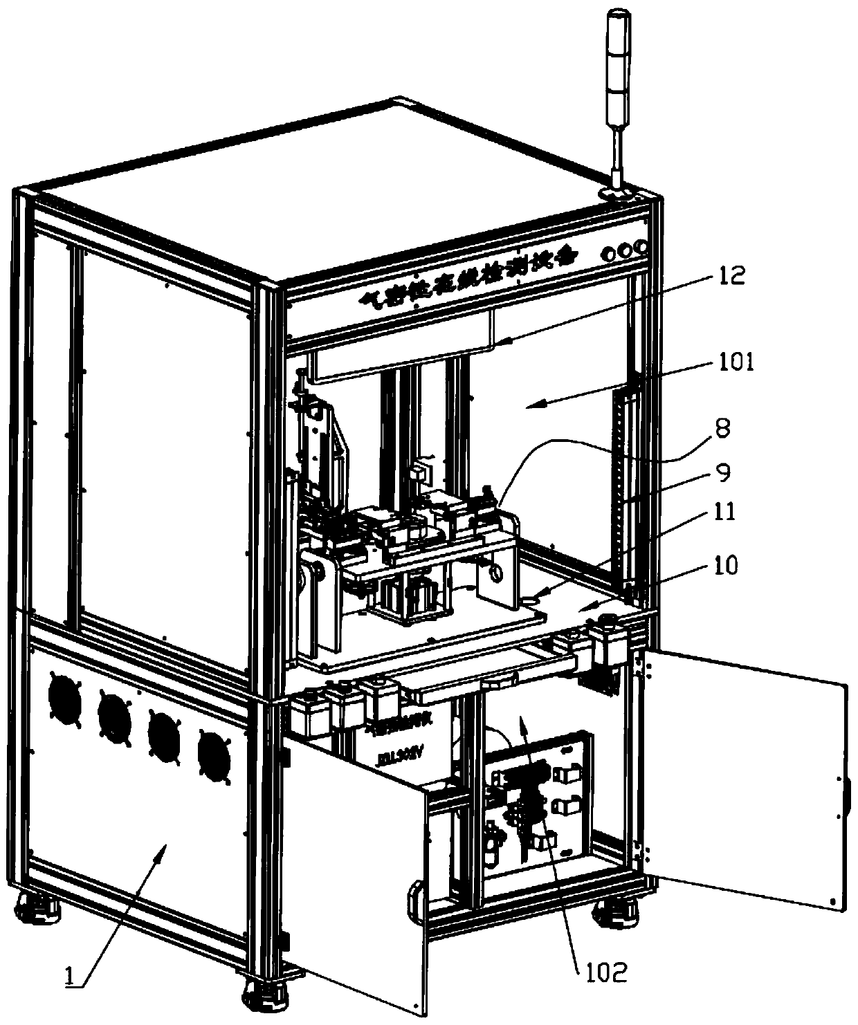
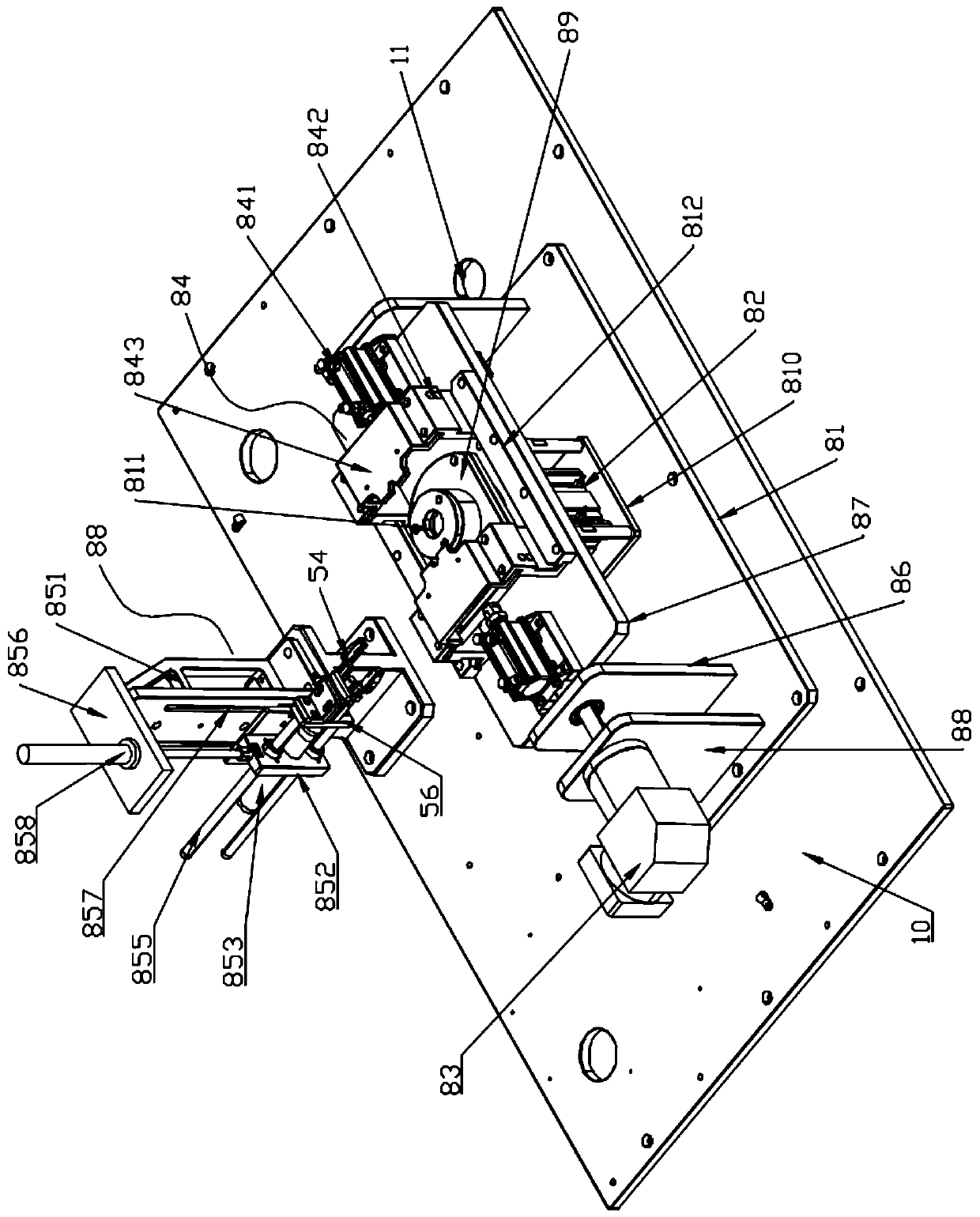
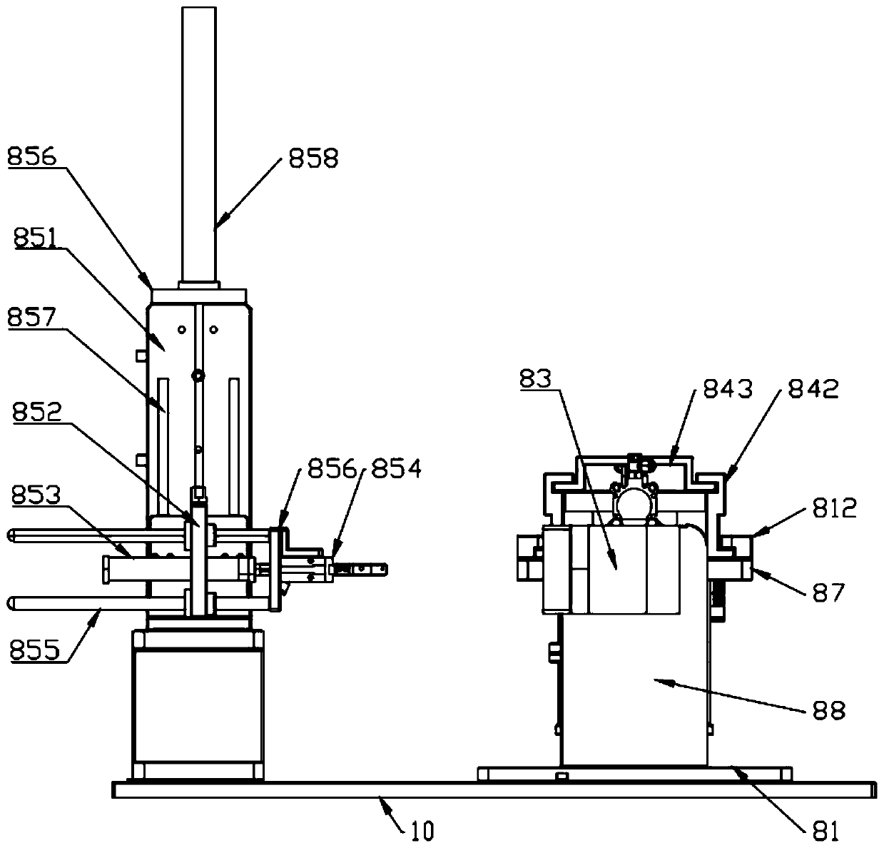
[0025] Such as Figure 1 to Figure 4 As shown, an airtightness detection device includes a frame 1, a test chamber 2, a vacuum generator 3, a leak detector 4, a flow controller 5, a flow sensor 6, an air pressure sensor 7 and a fixture assembly 8. The upper part of the rack is a test area 101, and the lower part of the rack is an equipment installation area 102. The vacuum generator 3, leak detector 4, flow controller 5, flow sensor 6, and air pressure sensor 7 are all installed in the equipment installation area 102. , the fixture assembly 8 is installed in the test area 101 and is used to fix the test chamber 2, and the product to be tested is installed in the test chamber 2.

[0026] In the present invention, the clamp assembly includes a base...


PUM


Abstract

The invention discloses a gas tightness detection device, related to the field of machinery. The gas tightness detection device comprises a frame, a test cavity, a vacuum generator, a leakage detector, a flow controller, a flow sensor, a gas pressure sensor and a clamp assembly, wherein an upper part of the frame is a test area, a lower part of the frame is a device mounting area, the vacuum generator, the leakage detector, the flow controller, the flow sensor and the gas pressure sensor are all mounted in the device mounting area, the clamp assembly is mounted in the test area and used for fixing the test cavity, and a to-be-detected product is mounted in the test cavity. According to the gas tightness detection device provided by the invention, a plurality of the detection devices are integrated in one frame, simultaneously, the corresponding clamp assembly is provided, diversified test requirements of client products are realized, the whole structure is compact and highly integrated, and visualized detection works are realized.

Description

technical field [0001] The invention belongs to the field of machinery, and in particular relates to an air tightness detection device. Background technique [0002] Air tightness testing equipment is mainly used for air tightness testing, negative pressure testing, flow testing and valve opening pressure testing of customer products. The current testing equipment more or less uses a single testing equipment for testing, and has not achieved integration. Although some intelligent testing equipment has appeared on the market, the integration level is still insufficient, and the testing chamber needs to be clamped and positioned before testing. , to ensure that the product is in a proper position when testing. The fixture structure of the existing air tightness testing equipment is single, and it is inconvenient to adjust the position of the product, which leads to a long time for clamping and positioning, and reduces the testing efficiency. Contents of the invention [00...

Claims


Application Information

Patent Timeline
IPC IPC(8): G01M3/26G01M13/00
CPCG01M3/26G01M13/00
Inventor 刘寅刘杰马德祥方经纬刘裕孙胜斌
Owner 安徽瑞佑自动化科技有限公司
Why Eureka
Try Eureka