Method for positioning grooves between building wallboards

A positioning method and wall panel technology, applied in the field of construction, can solve the problems of low adaptability, complex mechanism design, high hardware cost, etc., and achieve the effect of reduced hardware cost, simple and convenient mechanism design

Active Publication Date: 2019-11-12
GUANGDONG BOZHILIN ROBOT CO LTD
View PDF9 Cites 2 Cited by
  • Summary
  • Abstract
  • Description
  • Claims
  • Application Information

AI Technical Summary

Problems solved by technology

But the traditional positioning method makes the mechanism design

Method used


Image

  • Method for positioning grooves between building wallboards
  • Method for positioning grooves between building wallboards

Examples


Embodiment 1

[0042] This embodiment provides a method for locating grooves between building wall panels, which can directly and simply obtain the edge position of the grooves, which makes the equipment design simple and the hardware cost lower, and can adapt to the situation where the edge of the groove is incomplete or jagged, and the environment Light has a certain degree of anti-interference.

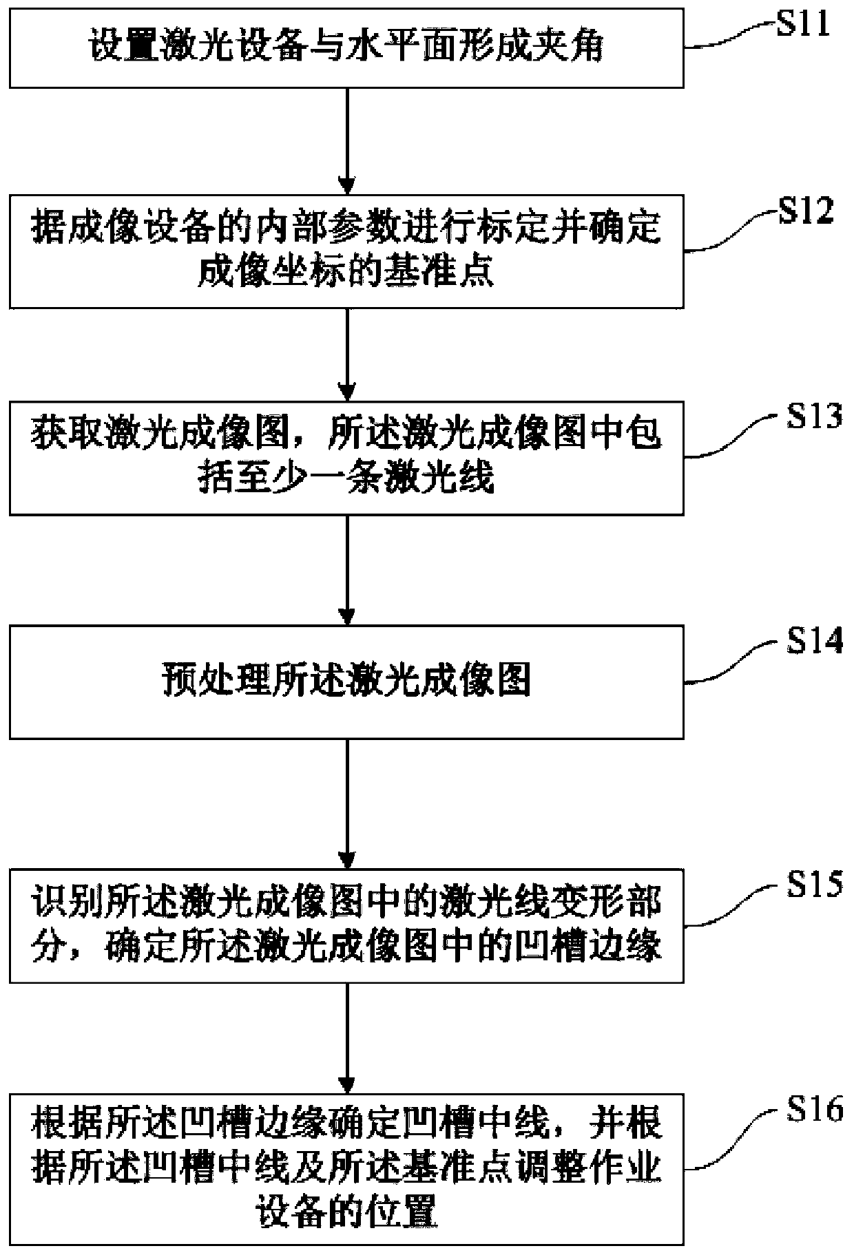
[0043] figure 1 It is a schematic flowchart of the method for positioning grooves between building wallboards provided by Embodiment 1 of the present invention. Such as figure 1 As shown, the positioning method includes the following steps:

[0044] S11, setting the laser device to form an angle with the horizontal plane.

[0045] At the same time, the laser device also forms an included angle with the wallboard. The laser device hits the laser line from a certain angle to the wallboard, and after passing through the wallboard, the information is fed back to the imaging device through diffuse ...

Embodiment 2

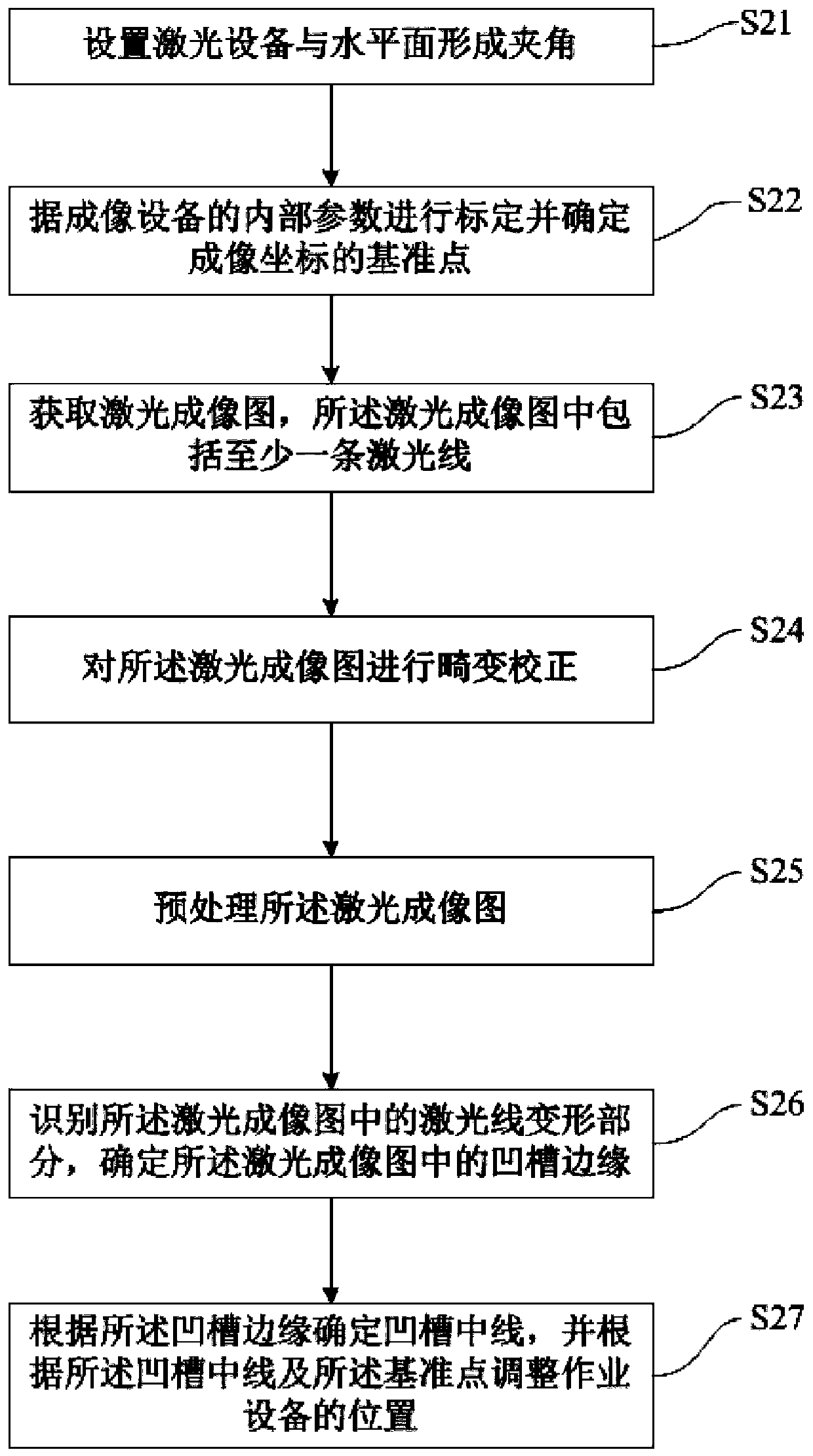
[0058] In this embodiment, on the basis of the foregoing embodiments, the methods for preprocessing and identifying deformation of laser lines are refined. figure 2 It is a schematic flowchart of a method for positioning grooves between building wall panels provided by Embodiment 2 of the present invention. Such as figure 2 As shown, the positioning method specifically includes the following steps:

[0059] S21, setting the laser device to form an angle with the horizontal plane.

[0060] S22, perform calibration according to internal parameters of the imaging device and determine a reference point of the imaging coordinates.

[0061] S23. Acquire a laser imaging image, where the laser imaging image includes at least one laser line.

[0062] S24. Perform distortion correction on the laser imaging image, so that the laser line becomes straight.

[0063] S25. Preprocessing the laser imaging image, so that the laser lines in the laser imaging image are easier to identify. ...


PUM


Abstract

The invention provides a method for positioning a groove between building wallboards. The method comprises the steps of arranging laser equipment to form an included angle with the horizontal plane; calibrating according to the internal parameters of the imaging equipment and determining a reference point of an imaging coordinate; obtaining a laser imaging graph, wherein the laser imaging graph comprises at least one laser line; preprocessing the laser image; identifying a laser line deformation part in the laser imaging graph, and determining a groove edge in the laser imaging graph; and determining a groove center line according to the groove edge, and adjusting the position of the operation equipment according to the groove center line and the reference point. According to the method for positioning the groove between the building wallboards, the groove can be simply positioned, the hardware cost is reduced, and the adaptability is improved.

Description

technical field [0001] Embodiments of the present invention relate to the field of building technology, and in particular to a method for positioning grooves between building wall panels. Background technique [0002] The traditional method of locating the groove between the boards is to find the groove of the two wallboards subjectively by combining with the machine and the subjective, and realize the positioning of the groove, and then manually fix one end of the net to be hung, straighten and then use the other end of the net The net falls completely within the groove. But the traditional positioning method makes the mechanism design complicated, the hardware cost is high and the adaptability is low. Contents of the invention [0003] The purpose of the embodiments of the present invention is to provide a method for positioning grooves between building wall panels, which can simply locate the grooves, reduce hardware costs and improve adaptability. [0004] To achieve...

Claims


Application Information

Patent Timeline
IPC IPC(8): G06K9/46G06K9/36G01S17/89
CPCG01S17/89G06V10/247G06V10/20G06V10/44
Inventor 李海彭博陈刚蒋星
Owner GUANGDONG BOZHILIN ROBOT CO LTD
Why Eureka
Try Eureka