Cable interface sealing mechanism and underwater power transformer

A technology of cable interface and sealing mechanism, which is applied in the direction of cable inlet sealing device, transformer/inductor parts, air-filled/oil-filled cable accessories, etc., which can solve the problems of damaged transformers, inconvenience of power transformers, and damaged transformers. Waterproof function, improved sealing effect, simple structure effect

Pending Publication Date: 2019-11-12
北京国电环网电气科技有限公司
View PDF0 Cites 3 Cited by
  • Summary
  • Abstract
  • Description
  • Claims
  • Application Information

AI Technical Summary

Problems solved by technology

However, in actual operation, when the power grid fails due to various reasons, the water pump cannot work, and the transformer will be flooded for a long time and be damaged.
According to statistics, a considerable part of my country's huge transformer production capacity is used for the annual replacement of damaged transformers, resulting in huge economic losses.
[0004] This shows that above-mentioned existing underground power transformer still has inconvenience and defective, and urgently needs to be further improved

Method used


Image

  • Cable interface sealing mechanism and underwater power transformer
  • Cable interface sealing mechanism and underwater power transformer

Examples


Embodiment Construction

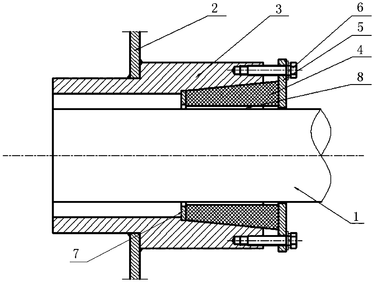
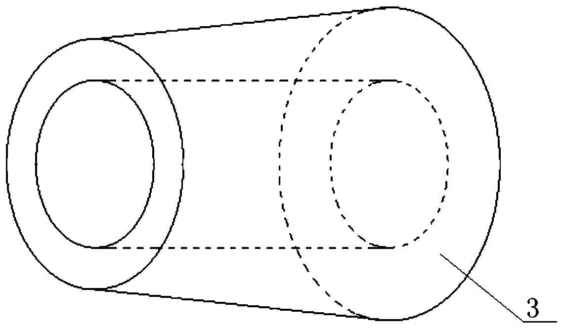
[0026] Refer to attached figure 1 and 2 As shown, the cable interface sealing mechanism of this embodiment is used to realize the sealing between the cable 1 and the inlet and outlet of the transformer box 2, which includes a cable inlet and outlet conduit 3, a flexible tapered sleeve 4, a locking compression ring 5 and a locking bolt 6 .

[0027] The cable inlet and outlet conduit 3 is fixedly connected to the inlet and outlet of the box body 2, and the connection between the cable inlet and outlet conduit 3 and the box body 2 is set in a right-angle step shape, which increases the contact area between the outer wall of the conduit and the edge of the inlet and outlet of the box body, and improves airtightness. sex. In this embodiment, the cable inlet and outlet conduit 3 is made of stainless steel pipe, and is fixedly connected with the inlet and outlet of the box body 2 made of weathering steel plate by welding. The inner side of the outer end of the cable inlet and outl...


PUM


Abstract

The invention discloses a cable interface sealing mechanism. The mechanism comprises a cable inlet and outlet conduit, a flexible conical sleeve, a locking compression ring and a locking bolt; the cable inlet and outlet conduit is fixedly connected with the box body inlet and outlet; the inner side of the outer end of the cable inlet and outlet conduit is set into a conical flaring structure; a cylindrical through hole is formed in the inner side of the flexible conical sleeve, and a cone matched with the cone-shaped flaring structure is arranged on the outer side of the flexible conical sleeve; the axial length of the flexible conical sleeve is greater than that of the conical flaring structure, the locking bolt is fixedly connected with the outer end face of the cable inlet and outlet conduit through a bolt through hole in the locking compression ring, and the flexible conical sleeve is tightly pressed between the cable inlet and outlet conduit and the cable through the locking compression ring under the action of the locking bolt to form sealing. A self-plastic sealing layer is arranged between the flexible conical sleeve and the cable. The invention further discloses an underwater power transformer adopting the sealing mechanism. Good sealing of the cable and the transformer box body can be achieved, and reliable guarantee is provided for an underwater power transformer which is truly immersed in water for a long time and operates safely.

Description

technical field [0001] The invention relates to the technical field of electric power assembly, in particular to a cable interface sealing mechanism and an underwater power transformer. Background technique [0002] The 10 / 0.4kV power transformer is an essential and important equipment in the power distribution system, and its operation reliability directly affects the safety of the power distribution system. The rainy climate and typhoon disasters in my country's coastal areas and south often bring huge losses to power distribution networks and large-scale and wide-ranging power transformers. [0003] In recent years, the concept of underground transformers has been proposed for power grid transformation in order to reduce the impact of the climate. However, such products can only be easily waterproofed and short-term flooded, and cannot solve the problem of transformers operating underwater for a long time, let alone withstand Prolonged immersion in flood waters. In orde...

Claims


Application Information

Patent Timeline
Patent Type & Authority Applications(China)
IPC IPC(8): H02G15/013H02G15/32H01F27/04
CPCH01F27/04H02G15/013H02G15/32
Inventor 姚志刚秦朋
Owner 北京国电环网电气科技有限公司
Why Eureka
Try Eureka