City road detecting robot system

A robot system and road detection technology, applied in the direction of roads, roads, road repairs, etc., can solve the problems of large limitations, inaccurate measurement data, inaccurate detection results, etc., to reduce level errors and slope errors, and facilitate The effect of actual use and accurate measurement data

Inactive Publication Date: 2019-11-15
南京宁政工程咨询有限公司
View PDF6 Cites 2 Cited by
  • Summary
  • Abstract
  • Description
  • Claims
  • Application Information

AI Technical Summary

Problems solved by technology

[0002] General municipal road detection mainly detects the slope and level of the road, etc., but the actual measurement data is generally obtained through manual measurement, which consumes a lot of human resources, and some of them rely on vehicles for detection, but vehicles can The reach area is limited, so the measurement data is not accurate;
[0003] For example, the patent No. CN108330792A - road inspection vehicle, the present invention relates to a road inspection vehicle, relates to the field of road inspection technology, solves the problem of low installation position and easy wear of detection equipment, including the vehicle body and the detection equipment arranged above the rear door box, the detection equipment box is provided with a connecting frame fixed on the car body, and the detection equipment is installed on the connecting frame, and the detection device includes a body, and the body is provided with a fixing part for connecting with the connecting frame , the two ends of the detection equipment are provided with laser emitters that emit laser downwards, and the two sides of the connecting frame are provided with windows for the laser to pass through, and a transparent protective plate is covered on the top of the window. This patent relies on Cars are used for detection, which is limited and the detection results are inaccurate

Method used


Image

  • City road detecting robot system
  • City road detecting robot system

Examples


Embodiment Construction

[0021] The present invention will be further described in detail below in conjunction with the drawings.

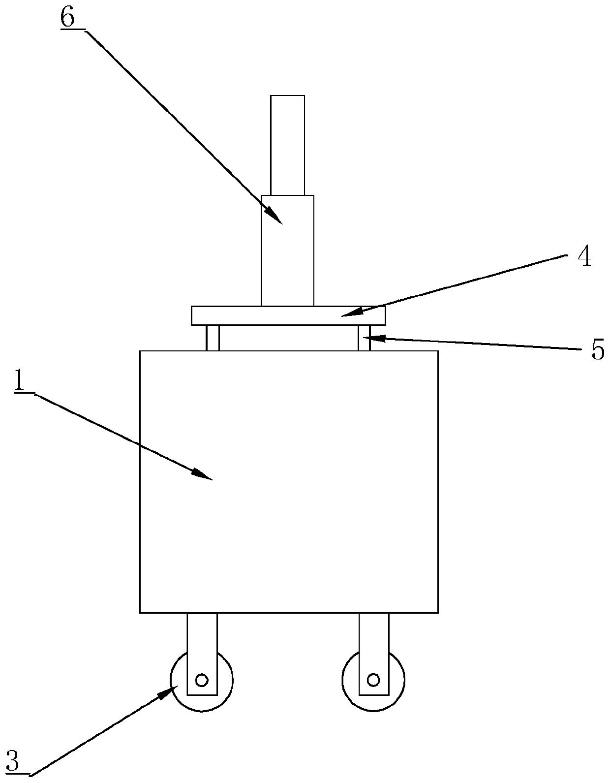
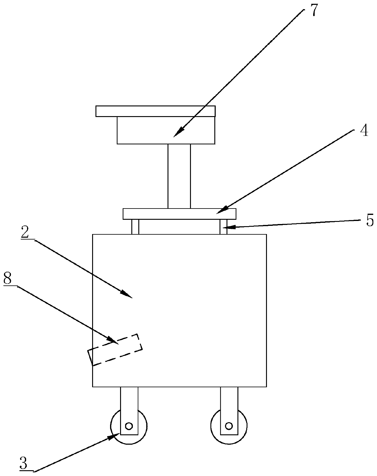
[0022] Such as figure 1 with figure 2 As shown, an urban road detection robot system includes a benchmarking robot and a detection robot that cooperate with each other. In the present invention, both the benchmarking robot and the detection robot are equipped with a GPS module, a wireless communication module, a vision detection module, a storage module, and a processor module. And the controller module is used to control the benchmarking robot and the detection robot so that the two can work together to achieve the detection of urban roads. The connections between the above modules are connected according to the actual working circuit to realize the ability of the urban road detection robot system Normal operation shall prevail.

[0023] Such as figure 1 with figure 2 As shown, the benchmarking robot includes a movable first independent chassis 1, a telescopic measurement...


PUM


Abstract

The invention relates to the field of municipal road detection and discloses a city road detecting robot system. The system solves the problems that when detecting is carried out by depending on vehicles, measuring and detecting are limited greatly, and measured data are not accurate. According to key points of the technical scheme, the city road detecting robot system comprises a marker post robot and a detecting robot which are used in cooperation. The marker post robot comprises a first independent case capable of moving. A measuring marker post capable of telescoping is arranged on the topof the first independent case. The detecting robot comprises a second independent case capable of moving. A levelness camera is arranged on the top of the second independent case. Horizontal supporting tables are arranged between the measuring marker post and the first independent case and between the levelness camera and the second independent case in a distributing manner correspondingly. The marker post robot and the detecting robot are each provided with a GPS module, a wireless communicating module, a processor module and a controller module which are connected correspondingly. By the adoption of the robots, all directions of a road can be reached, and the detecting result is accurate.

Description

Technical field [0001] The invention relates to the field of municipal road detection, and more specifically, it relates to an urban road detection robot system. Background technique [0002] General municipal road detection mainly detects the slope and levelness of the road, but the actual measurement data is generally obtained through manual measurement, which consumes a lot of labor resources, and some of them rely on vehicles for detection, but vehicles can The area reached is limited, so the measurement data is not accurate; [0003] For example, the patent of the announcement number CN108330792A-road inspection vehicle, the present invention relates to a road inspection vehicle, which relates to the technical field of road inspection, and solves the problems of low installation location and easy wear of the inspection equipment, including the vehicle body and the inspection equipment installed above the rear door A box, the detection equipment box is provided with a connecti...

Claims


Application Information

Patent Timeline
Patent Type & Authority Applications(China)
IPC IPC(8): E01C23/01G01B11/30G01C9/00
CPCE01C23/01G01B11/30G01C9/00
Inventor 冯永进郭东升顾用斌
Owner 南京宁政工程咨询有限公司
Why Eureka
Try Eureka